By Nikita Lambert – Certified SOLIDWORKS Expert (CSWE) at SolidXperts
You may have already said that your rendering is acceptable, but that it seems to be missing something, that your image lacks life. SOLIDWORKSVisualize now has the solution for you: You can now create a video decal and apply it to any surface of your model. For example, a cellphone company could put a clip showing the operating system in action on a newly designed device, an animated background plan outside a window, or even a television playing your favorite series! The possibilities are limited only by your imagination.
To take advantage of this 2019 innovation, simply go to your Appearances tab, Add, New Decal, and finally Video. Browse and search for your video file and you need only apply it to your project.
SolidXperts teams can help you become true 3D experts! An additional question? Need information?
By Nikita Lambert – Application Specialist at SolidXperts
Nvidia has developed a collaboration platform to allow engineering, sales, marketing, and management teams to interact with a design still in the development phase, using virtual reality technology.
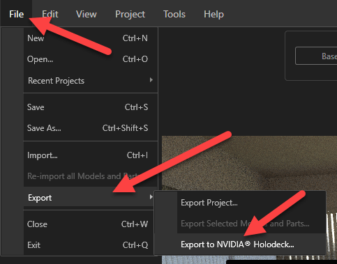
This platform allows you to transport yourself to the interior of a 3D modeled building, in front of a podium showcasing your newest products, or even into a virtual meeting room with your VR headset. SOLIDWORKS Visualize can export your completed project to an Nvidia Holodeck-supported format.
All appearances, environments, and lighting will be automatically recorded, all you have to do is explore the almost infinite possibilities of this new mode of communication.
SolidXperts teams can help you become true 3D experts! An additional question? Need information?
If you use tasks in PDM, SW to PDF file conversion for example, during a New Version or Service Pack update the PDM Administrator must also update the add-in tasks to take advantage of new features, improvements, or fixes. The same procedure applies to updating the basic programming add-in, Dispatch.
Here’s how to do it:
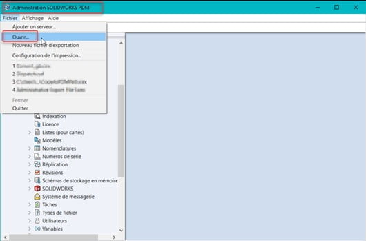
PDM Administration Tool > File > Open:
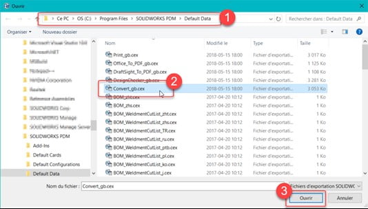
Go to > C:\Program Files\SOLIDWORKS PDM\Default Data
Open > C:\Program Files\SOLIDWORKS PDM\Default Data\Convert_gb.cex
Here are the complements available and the associated tasks:
To update Dispatch, open Dispatch.caf
Drag and drop SWTaskAddIn (import only the add-in) from the window on the right, in Add-ins on the left:
Note: If you have a dedicated workstation that performs tasks, you will need to log out and reconnect to PDM to ensure that you have the correct add-in.
Reply Yes to ‘Do you want to replace with the new object?’
It’s that simple. The add-in is now up-to-date!
SolidXperts teams can help you become true 3D experts! An additional question? Need information?
The SolidXperts Technical Support Team is here to assist with software installations and updates for all clients who have purchased a license with us.
You can contact us by telephone at: 1-877-824-3324, by email: soutien@solidxperts.com, or simply submit a request in the Client Portal: https://solidxpertsportal.force.com/support/portal_login
Ask us to send you our direct download link for installation files without having to go through the SOLIDWORKS site. Then if you wish, contact us for remote assistance with a member of our support team. We can remotely control your computer if you are not very familiar with the installation process or simply because you want a state-of-the-art installation!
We can take this opportunity to install our UtilsXperts toolbox, developed by our team of programmers at SolidXperts. You will be able to optimize your productivity and design products more efficiently, faster, and more profitably.
SAVE TIME!
For an additional fee, we also offer a hassle-free service to help you centralize your data in order to facilitate the management, customize your settings, and also standardize your data, BOM tables/revisions, and default models for better collaboration within your Engineering team, across your entire CAD system. Contact a Support Team member today for more information!
Rather than waste time with lengthy installations on all your stations, let us do it for you!
Do you work in cabinetmaking and often have repetitive programming tasks (CAM)? Would you like to know how to automate the g-code generation for the furniture you’ve designed? Would you like your CAM software to recognize the features of your SOLIDWORKS part automatically instead of having to program the g-code for each of your parts manually?
If so, read on and learn what SWOOD CAM can do for you.
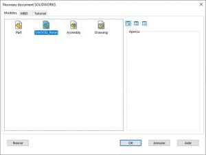
SWOOD CAM is an application integrated into SOLIDWORKS that adds CAM functionality directly into SOLIDWORKS. SWOOD CAM is designed specifically for woodworking and supports many different machines used in the industry.
In order to take full advantage of SWOOD CAM, we must first define which tools will be used for each of the operations to be performed on a part.
This is the case for most CAM software currently on the market. However, SWOOD CAM goes a step further by also offering you the possibility to program automatic operations into your SOLIDWORKS document template.
These automatic operations inform SWOOD CAM which tools to use to achieve different pockets, contours, holes, and other features on or in your parts. Saw aggregate cutting operations, drilling with drilling blocks, machining, and many other operations are supported by SWOOD CAM.
Supported functions include:
Automatic contouring
Automatic pockets
Automatic drilling
Automatic slots
Automatic cutting
Once this programming is done and saved in your SOLIDWORKSdocument templates, SWOOD CAMwill be able to detect the various functions you have inserted into your parts and generate the necessary g-code automatically. The option is always available to manually program operations if you want more control, but SWOOD CAM can automate all programmed operations. Additionally, you can run a simulation for these operations in order to see the end product on your computer screen before sending the code to your machine.
SolidXperts teams can help you become true 3D experts! An additional question? Need information?
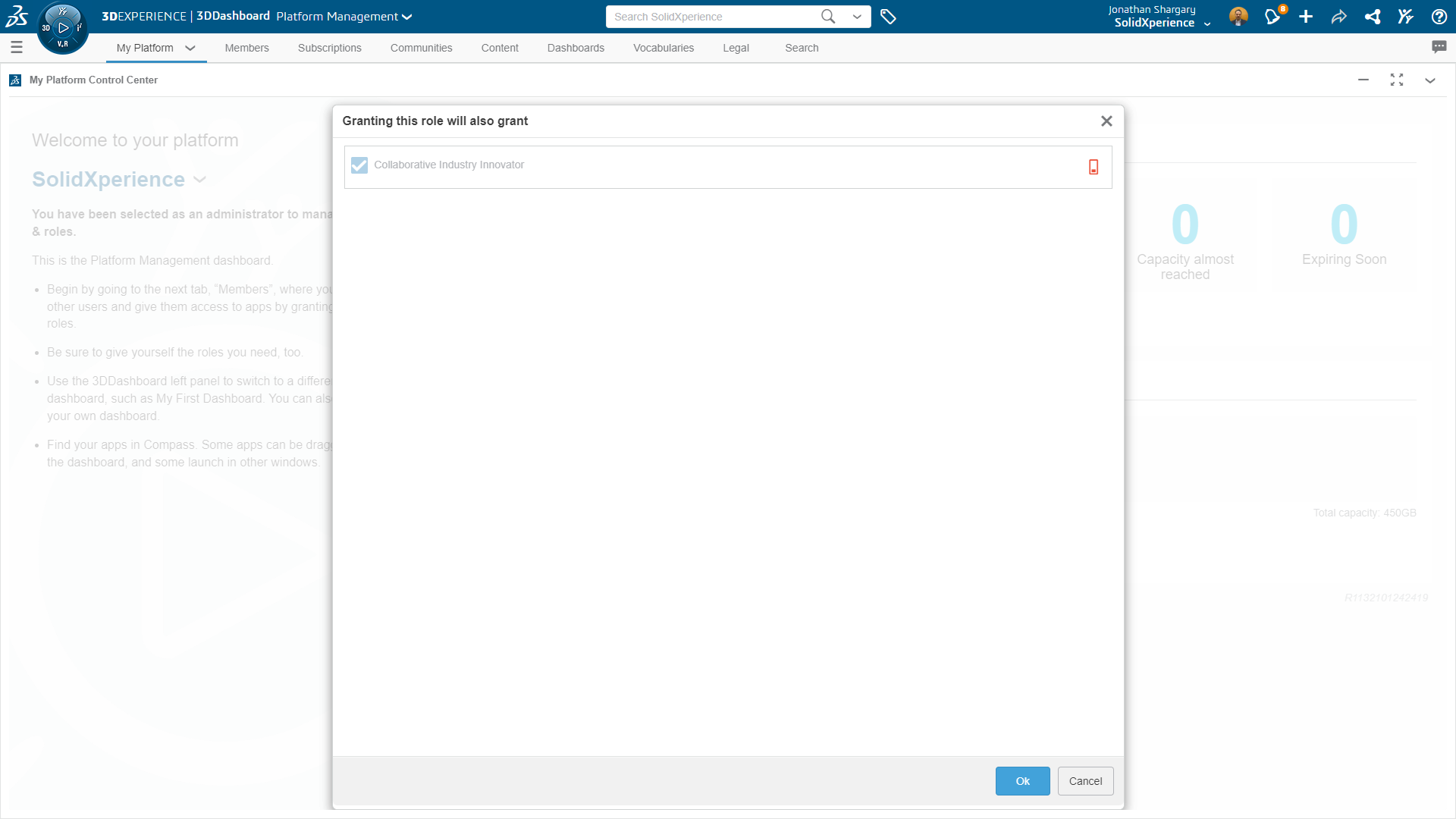
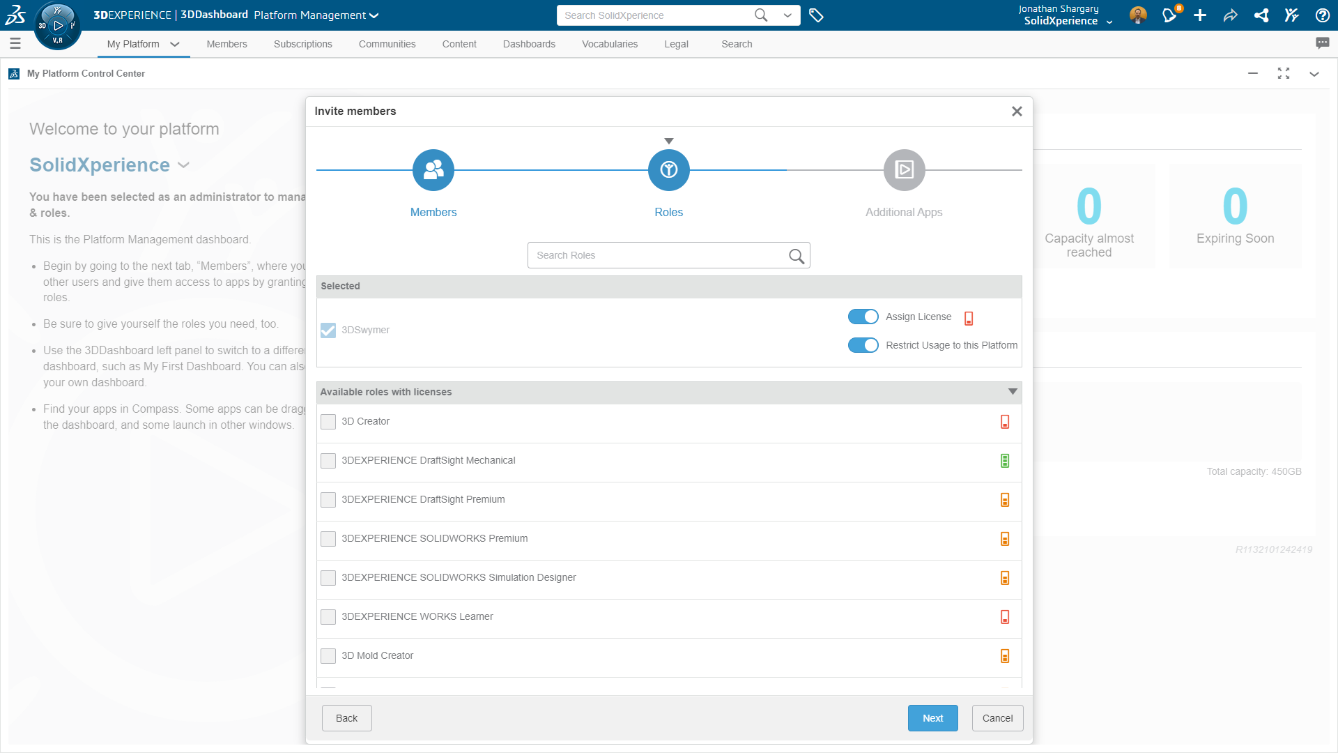
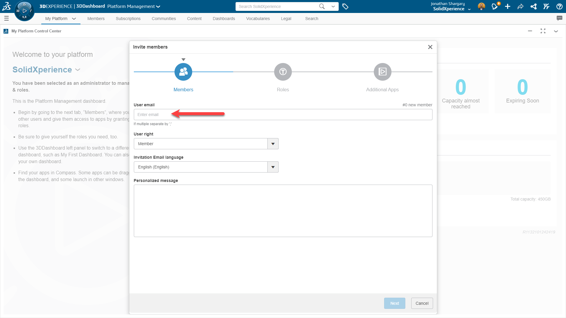
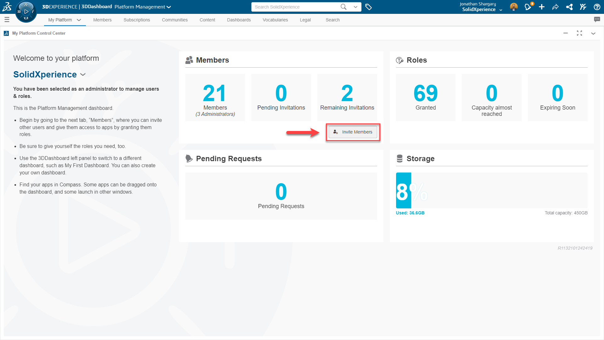
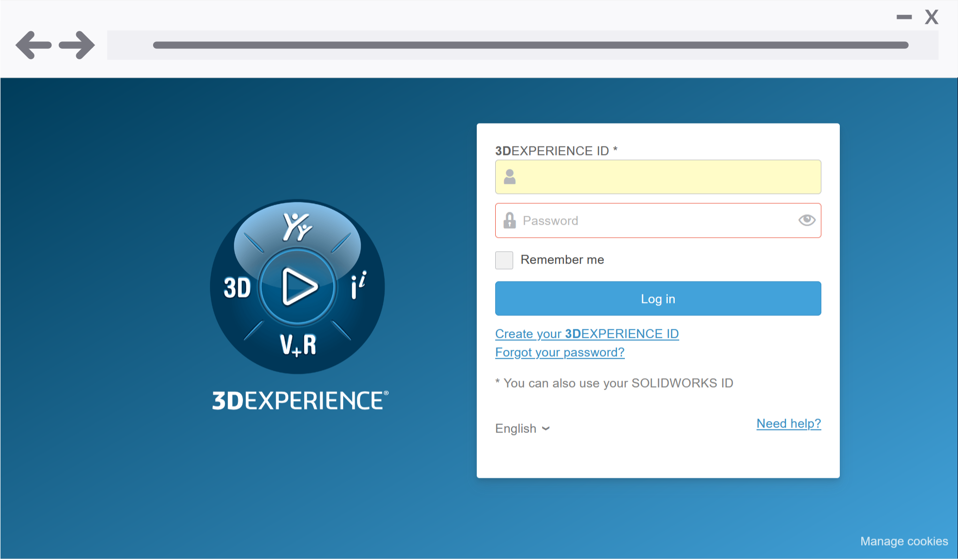
Did you know that you can access and use your SOLIDWORKS from anywhere? Users can simply log in with their SOLIDWORKS ID on the MySolidworks website and launch their SOLIDWORKS! SOLIDWORKS online licensing is available to all customers regardless of their subscription status. The SOLIDWORKS Admin can reassign an Online License at any time, as long as the license is not in use by the user.
SOLIDWORKS online licensing is a new model that ties one or more licenses of SOLIDWORKS products to a user’s SOLIDWORKS ID. With SOLIDWORKS online licensing, users have the flexibility to install and use SOLIDWORKS products on as many machines as they wish, without having to activate or deactivate machines every time. SOLIDWORKS’ customers can access all the products they are entitled to by simply login in using their SOLIDWORKS ID. All they need is a connection to the internet.
The Admin can select an asset and change it back from online licensing to machine activation at any time using the toggle option in the detailed product page if the license is not in use by the user.
SolidNetWork Licenses are ideal for medium to large size companies that want to share a pool of licenses over multiple users. On the other hand, single-user licenses with SOLIDWORKS online licensing are ideal for individuals that have their own license and want the flexibility to use SOLIDWORKS on multiple machines.
Only one user can be assigned to an Online License product.
SOLIDWORKS online licensing is available for the following single-user license products:
**Perpetual and temporary licenses are supported. SOLIDWORKS PDM and SolidNetWork Licensing (SNL) are not supported with online licensing. Home Use Licenses (HULs) are not currently supported.
Don’t hesitate to call the Technical Support Call Center and let us do it for you!
One of our specialists can help you configure it remotely.
Any questions? Need help? Ask one of our experts.
Whether you’re ready to get started or just have a few more questions, you can contact us toll-free:
New metal 3D printing systems are available with a much lower price point and the ability to produce parts in a growing range of alloys. This is making metal 3D printing a valid option for manufacturing firms much smaller than the aerospace companies usually associated with metal printed components.
Custom Power Train
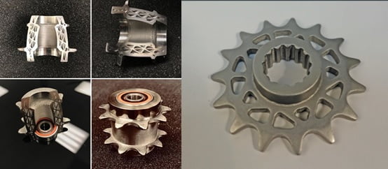
BowHead Corp produces the Reach adventure cycle that allows disabled persons to enjoy mountain bikes or similar trail systems. The custom power train components are metal 3D printed.
The printed drive and idler sprockets are lighter weight than a machined equivalent and have held up to severe off-road trail conditions. Metal printing allows for customization of sprocket spacing and OD which can be difficult to obtain with standard off-the-shelf components.
3D printed end effectors are a popular user upgrade or customization for traditional manufacturing pick & place robots. For gripping on parts with internal course threads or other hard-to-handle surfaces, a custom-fit set of gripper fingers can be easily printed in metal.
Cast No Doubt
Sometimes the anticipated annual product quantity does not readily justify the expense and inventory issues of minimum casting runs. This is an area where the option to metal 3D print a component can have significant savings. Properly designed for the 3D metal printing process, a component can combine features that might otherwise require additional fasteners and assembly work.
These are just a few samples of the components that can be quickly and easily produced with Metal-X 3D printing. The range of metal alloys available to print is growing every few months. Currently, it includes stainless steel (17-4), tool steel (H-13, A2, D2), and Inconel (625). Additional stainless steels, Copper, and Titanium are in development. The ability to quickly and inexpensively print metal components will spur further innovation in design and help to bring production local to where it is used.
John Nolin
Senior Technical Representative
SolidXperts USA
Metal-X Certified Technician
SolidXperts teams can help you become true 3D experts! An additional question? Need information?
Do you want to avoid designing sheet metal parts beyond the dimensional limits available? Add an alert (sensor) to your SOLIDWORKS model.
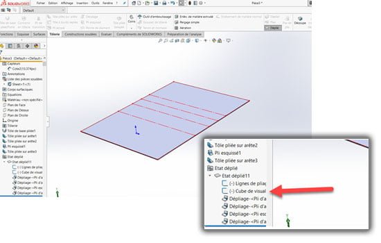
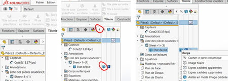
Step 1: Display the View Orientation Cube
Display the flattening of your sheet metal part. Make sure the sketch of the viewing cube is not in hidden mode.
Step 2: Hide the Volume Body
Hide the solid body to show only the fold lines and the viewing cube of the unfolded part. To do so, unfold the display status bar in the creation tree (Feature Manager). Right-click on the body displayed in the open tab and select hide volume body.
Step 3: Place a Reference Dimension
Now you can see the sketch of the viewing cube automatically created by a sheet metal part in SOLIDWORKS. This represents the overall volume of the part and you can place a reference dimension on the length, width, or thickness. Be careful not to select sketches that represent bend lines.
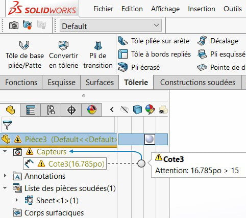
Step 4: Create a Dimension Sensor
Include a sensor. Right-click on the sensor icon in the creation tree and select “Add a sensor”. Select a dimension sensor and submit the desired conditions.
Sensor type = Dimension
Properties = Select the reference dimension that has been added (13.37″)
Alert = Check the box “Warn me if the value = …”
Select “is greater than” and write the value not to be exceeded. (15″ in the example)
Step 5: Check Sensor Operation
Finally, display the volume body again, and apply any modifications to your part in the folded state. A warning message is then displayed in the shaft if you are no longer within the defined values of the sensor.
SolidXperts teams can help you become true 3D experts! An additional question? Need information?
Contact us!
SolidXperts team is always there for you!
Any questions? Need help? Ask one of our experts.
Whether you’re ready to get started or just have a few more questions, you can contact us toll-free:
St. Laurent. April 3, 2020 – A journey of a thousand miles starts with just one step. For The SolidXperience Group, that step happened on March 21st, 2020 on a couch in the socially distant living room of CEO, Alex Habrich. While watching the news with his wife, Susie, both growing increasingly concerned with the spread of COVID-19, she came across an advertisement for the Code Life Ventilator Challenge. Knowing him and the abilities of the people he employs, it was the perfect opportunity. “I know you can do this – go save lives”. That was all it took!
Our directive was clear: Design a low-cost, simple, easy-to-use, and easy-to-build ventilator that could serve COVID-19 patients, as quickly as possible. The following day Alex asked for volunteers, and a diverse team was curated from three companies and various backgrounds.
“This project is a collaboration of people from both Canada and the United States, with everyone teleworking!” – Alex P. Habrich, The SolidXperience Group CEO
Within 24 hours a team was gathered, within 8 days the designs were submitted to the challenge hosts, and within a month The SolidXperience Group will be testing a fully functional prototype of the complete OXYGEN field-ready ventilator system.
“It feels like drowning is”, the most common report from the COVID-19 patients requiring breathing assistance, and with that imagery, we took inspiration from the simplicity of a scuba breathing apparatus. The SolidXperience Group officially began tackling the problem on March 23rd, ready to help save the world however they could.
The group quickly decided the best course of action would be to produce a machine that could both conventionally connect in a hospital setting and run as a stand-alone unit in developing countries or emergency overflow.
The next step was to analyze the given product specifications and start creating schematic diagrams defining the required parts and showing how those parts interact to create the desired results. With the help of the project’s panel of medical advisors, the group was able to take the initial schematic designs and modify them as a collaborative team. All online!
Then commenced several fast-paced days of editing, revision, discussion, and decision. Affordability always being a key factor. The device needed survivability, an intuitive setup and user interface, easily maintained and replaceable parts, and it needed to be kept as inexpensive to manufacture, in mass, as possible. This iterative process proceeded until March 29th at which time schematics were finalized. With the engineering in place, product design took off.
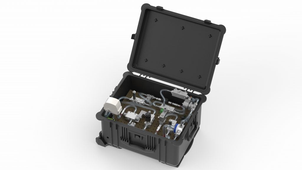
Next, packaging: getting all the required components to fit into a manageable, transportable, robust, easy-to-operate, and reliable case. Under the pressure of the CODE LIFE contest entry submission date of March 31st, this process was successfully started and completed on March 30th. Concurrently, the digital interface was coded to manage the internal valves, solenoids, and sensors necessary to provide a clear and secure on/off readout and warning alarms.
11:58 p.m. March 31st, 2020 – The SolidXperience Group successfully submitted their entry to the CODE LIFE Ventilator Challenge and walked away with a new purpose.
Inspired by how quickly and efficiently his team was able to redesign the ventilator system while physically separated and baffled by the inflated asking price for current machines, Alex decided regardless of the outcome of the contest, The SolidXperience Group would produce their more reliable and less expensive ventilators.
The fight isn’t over yet, however! In the coming weeks, several more steps need to be taken quickly to meet the hopeful deadline of May 1st for a functioning prototype. As the physical pieces of the first construction are gathered the interface code must be tested and refined, and the assembly must go through a series of tests and simulations to determine that it meets pre-set standards and can be labeled ‘medical grade’.
Both companies in The SolidXperience Group, SolidXperts, and Mecanica Solutions, eagerly look forward to stepping out into the world, continuing our thousand-mile journey, and doing what we can to help save lives all over the world.
Thank you to the following team members and professionals for their part in the success of this project!
Here is a new visualization tool for your SOLIDWORKS assemblies related to values from your PDM. As an example, rapidly visualize the parts that are “for approval”. Identify the parts “suppliers” vs “fabricated” parts. See in a glimpse the parts that are specific to a PDM category. All this is in the SOLIDWORKS graphic window.
This tool allows the selection of a categories list, workflow, and variables present in the vault and visualizes the parts that correspond to those criteria in SOLIDWORKS. It is also possible to assign colors to the components that contain those criteria.
Here are two ways to identify the parts in an assembly:
Assign a color to a component based on a category, a workflow status, or a variable in an assembly.
Show Parts of an assembly based on the PDM search window
Display State Creation
When you will define your search criteria and visualization in the tool panel it will create the display states in SOLIDWORKS.
In the SOLIDWORKS file, a display state will be created for each category, workflow, and variables for which at least one value and one color has been pre-assigned in the Administration window.
The color will appear in the selected assembly parts.
Example: The colors have been assigned in the image below based on values and colors assigned by supplier name.
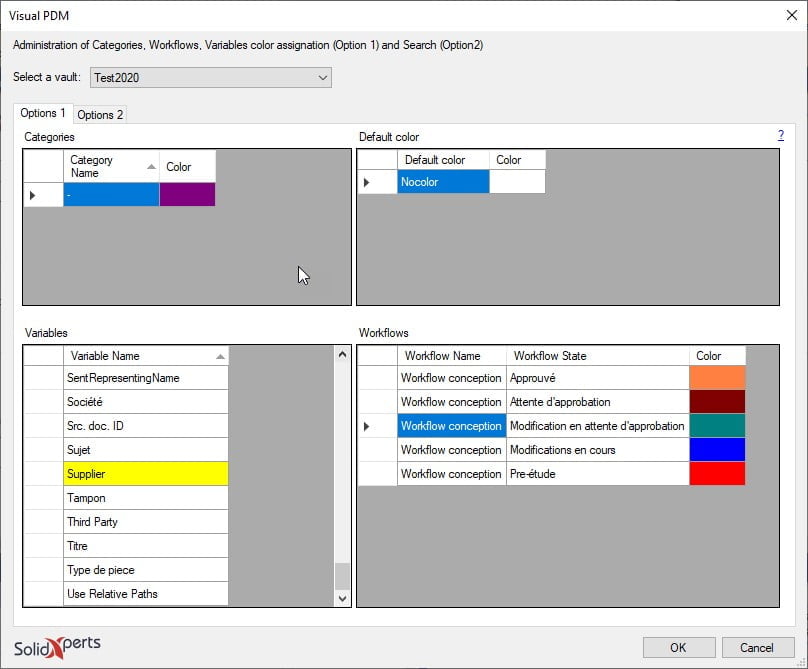
Administration Window
The administrator assigns a color to different items based on the requirements in the administration window by clicking on the variable name or in the “Color” field for “Categories”, “Workflow” or “Color by default”. When the tool is used, this tool creates different display states depending on which item(s) such as “Categories”, “Workflow” or “Variables” had a modification performed upon. The association between a value associated with the component will assign different colors to the parts as predefined in the administration window. The yellow color appears in the “Variable” window when a line had a value and color assigned.
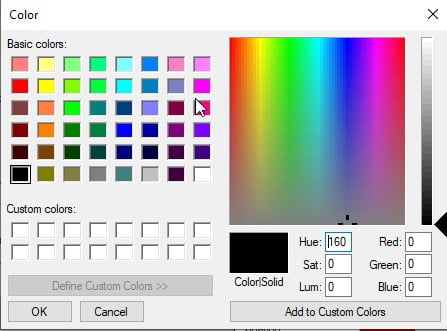
Here is the window that opens to allow you to key in the value and select the “Color” cell.
By clicking in the “Color” cell you obtain the following window to be able to select the desired color. Click on “Define Custom Colors“ to see the right end side of the window below.
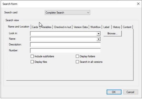
You key in the information in one or many fields of the PDM search window to create the selection criteria of the parts. Those parts will therefore be selected and visible in the SOLIDWORKS environment.
NOTE: THE SEARCH FIELDS IN THE TABS “NAME AND LOCATION”, “CHECKED IN/OUT”, “VERSION DATA” AND “WORKFLOW” ARE THE ONES AVAILABLE TO DEFINE A SEARCH CRITERIA.
Search Window
SolidXperts teams can help you become true 3D experts! An additional question? Need information?
Option 1: For licenses <1 year expired( Pay 2 Years Forward Upfront )
Get back on track with SOLIDWORKS CAD w/Cloud Services. By paying upfront for the next two years, you not only regain access to the powerful features of SOLIDWORKS but also enjoy cloud services to boost collaboration and efficiency.
Promotion Perks:
No need to worry about backdating and penalties. We’ll waive them for you!
Regain access to your design projects and continue where you left off, without any interruptions.
Option 2: For licenses >1 year expired ( Pay 3 Years Forward Upfront )
If your license has been expired for over a year, we understand the urgency to get back in the game. With this option, you can secure SOLIDWORKS CAD ALC w/Cloud Services.
Promotion Perks:
Our team is here to support your reintegration process, and we’ll waive backdating and penalties for a smooth transition.
Take advantage of the comprehensive SOLIDWORKS suite and unleash your creativity with the latest tools and features.
Option 1: Upgrade to 3DEXPERIENCE SOLIDWORKS
Seamlessly transition from SOLIDWORKS Desktop to 3DEXPERIENCE SOLIDWORKS, and experience a new dimension of design and collaboration. With secure cloud data management, increased collaboration capabilities, and reduced IT administration, 3DEXPERIENCE SOLIDWORKS empowers your team to work smarter and faster.
Option 2: Upgrade to SOLIDWORKS TERM w/Cloud Services
Opt for SOLIDWORKS TERM with Cloud Services, a flexible and convenient option that combines the power of SOLIDWORKS with the benefits of cloud-based solutions. Say goodbye to traditional licensing hassles and welcome easy deployment and automatic updates for a seamless design experience.
Promotion Perks:
This promotion covers both Standalone and Network licenses (SNL), making it suitable for businesses of all sizes.
Take advantage of the promotion price and add as many new licenses (3DEXPERIENCE SOLIDWORKS or SOLIDWORKS TERM w/Cloud Services) as you need on the same Purchase Order, with no limit on extra seats.
Enjoy the promotion discount for 3 years, whether purchased annually or upfront.
Even after the promotion period, you’ll continue to benefit with a 25% discount on successive years.
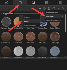 To take advantage of this 2019 innovation, simply go to your Appearances tab, Add, New Decal, and finally Video. Browse and search for your video file and you need only apply it to your project.
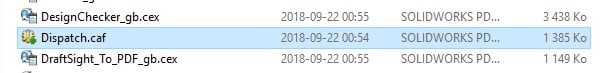 To update Dispatch, open Dispatch.caf
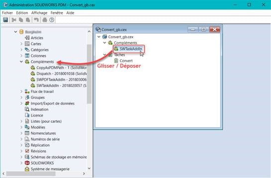 Drag and drop SWTaskAddIn (import only the add-in) from the window on the right, in Add-ins on the left:
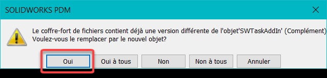 Note: If you have a dedicated workstation that performs tasks, you will need to log out and reconnect to
 The SolidXperts Technical Support Team is here to assist with software installations and updates for all clients who have purchased a license with us.
 SAVE TIME!
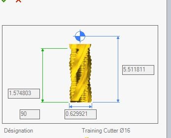
 These automatic operations inform SWOOD CAM which tools to use to achieve different pockets, contours, holes, and other features on or in your parts. Saw aggregate cutting operations, drilling with drilling blocks, machining, and many other operations are supported by SWOOD CAM.
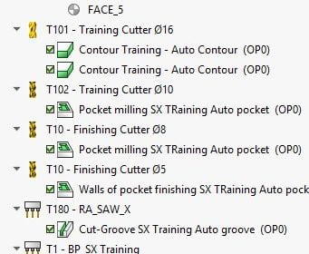 Once this programming is done and saved in your
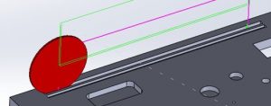

 A Better Grip
 Step 3: Place a Reference Dimension
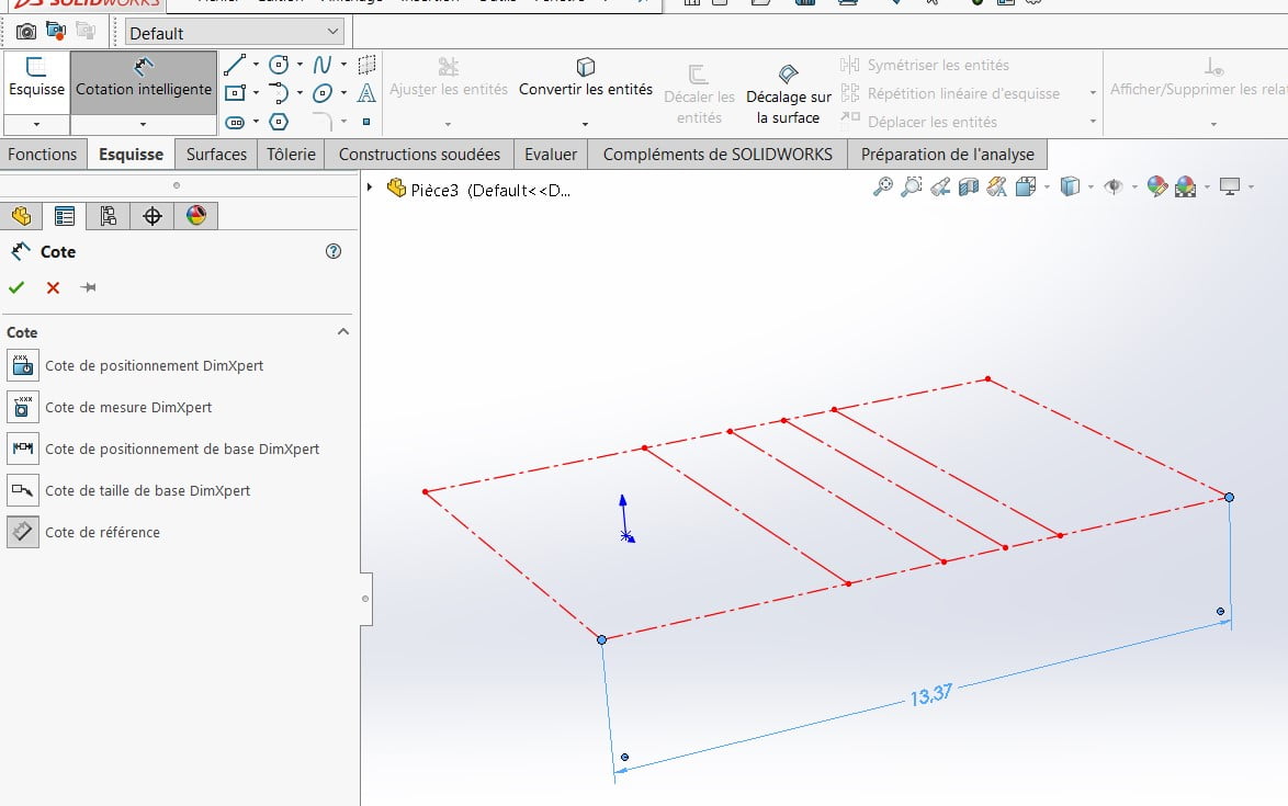 Step 4: Create a Dimension Sensor
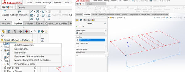 Step 5: Check Sensor Operation
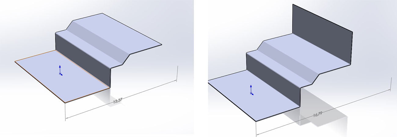
 “It feels like drowning is”, the most common report from the COVID-19 patients requiring breathing assistance, and with that imagery, we took inspiration from the simplicity of a scuba breathing apparatus. The SolidXperience Group officially began tackling the problem on March 23rd, ready to help save the world however they could.
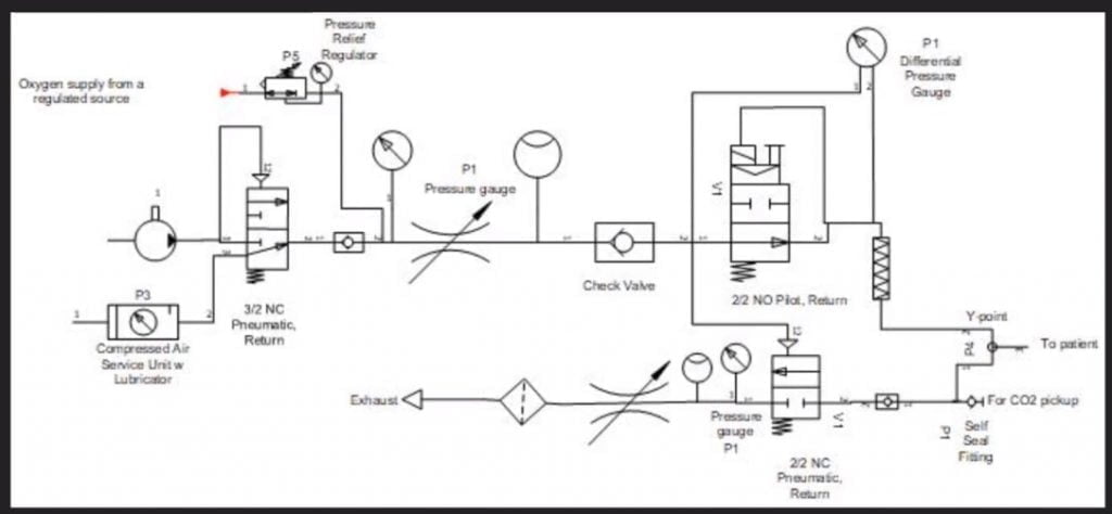 The next step was to analyze the given product specifications and start creating schematic diagrams defining the required parts and showing how those parts interact to create the desired results. With the help of the project’s panel of medical advisors, the group was able to take the initial schematic designs and modify them as a collaborative team. All online!
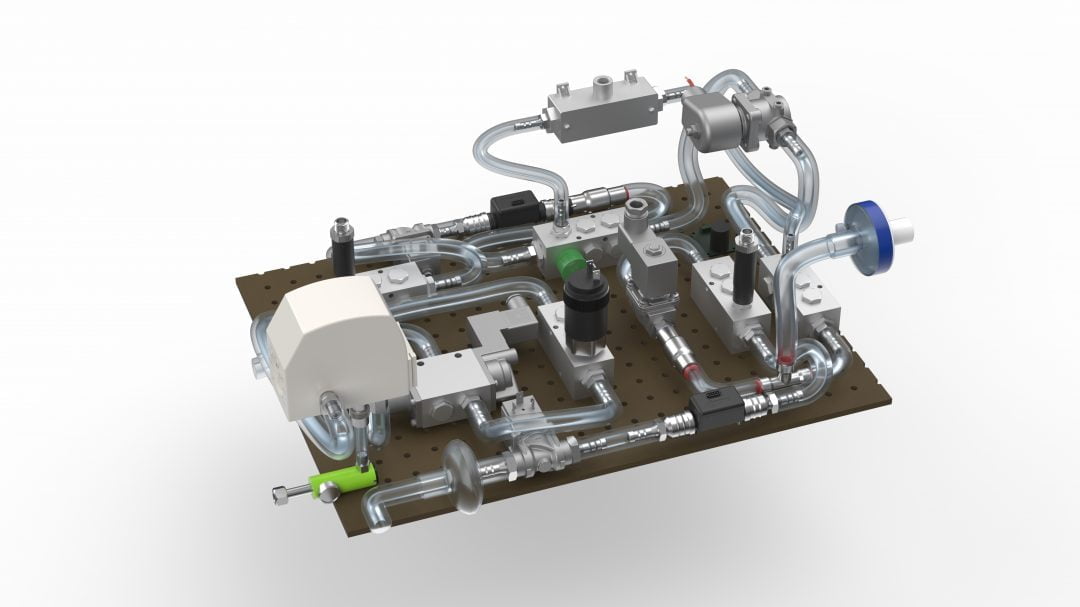 Next, packaging: getting all the required components to fit into a manageable, transportable, robust, easy-to-operate, and reliable case. Under the pressure of the CODE LIFE contest entry submission date of March 31st, this process was successfully started and completed on March 30th. Concurrently, the digital interface was coded to manage the internal valves, solenoids, and sensors necessary to provide a clear and secure on/off readout and warning alarms.
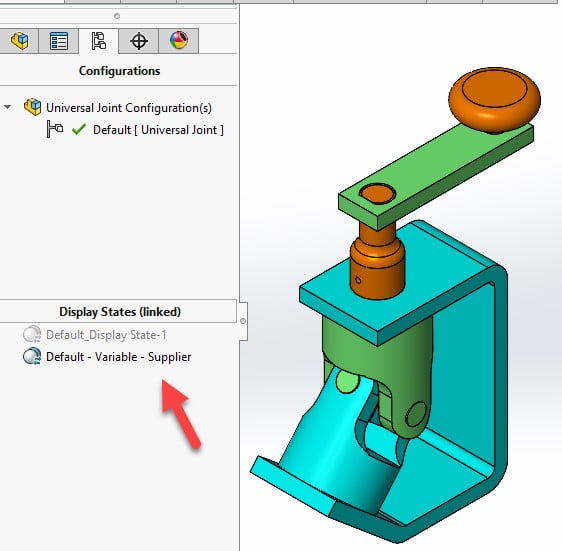
 Here is the window that opens to allow you to key in the value and select the “Color” cell.
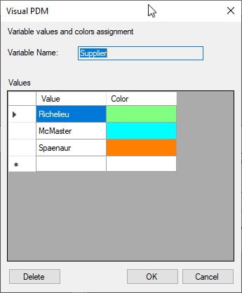 By clicking in the “Color” cell you obtain the following window to be able to select the desired color. Click on “Define Custom Colors“ to see the right end side of the window below.