Introduction
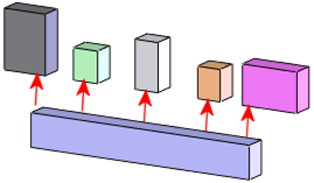
As a SOLIDWORKS user, you’re probably familiar with mates – those powerful tools that allow you to define relationships between components in an assembly. But have you explored the full potential of SmartMates?
In this article, we’ll dive deep into SmartMates and advanced assembly techniques to help you create robust assemblies efficiently.
What are SOLIDWORKS SmartMates?

SOLIDWORKS SmartMates are a feature within the SOLIDWORKS CAD software that streamline the assembly process by automatically creating mates (relationships) between components. This helps in positioning and orienting parts correctly within an assembly with minimal user intervention. Here’s a detailed look at how SmartMates work and their benefits:
How do SmartMates work?
- Automatic Detection: When you drag a component into an assembly, SOLIDWORKS automatically detects potential mating surfaces or edges.
- Contextual Menu: If a suitable mate is found, a contextual menu appears, suggesting possible mate types such as coincident, concentric, or tangent.
- Quick Application: By simply dropping the part near the desired location, SmartMates can apply the mate instantly, reducing the need for manual selection and confirmation steps.
What types of SmartMates are there?
- Coincident Mates: Aligns two faces, edges, or points so that they lie on the same plane.
- Concentric Mates: Aligns two cylindrical faces so that they share a common centerline.
- Tangent Mates: Ensures that a cylindrical face touches a planar face or another cylindrical face.
- Distance Mates: Maintains a specified distance between two components.
- Angle Mates: Maintains a specified angle between two components.
Understanding How to Use SmartMates
Imagine you are assembling a mechanical assembly consisting of a shaft and a bearing. Using SmartMates, you can quickly drag the bearing towards the shaft, and SOLIDWORKS will suggest a concentric mate, aligning the bearing with the shaft’s centerline automatically.

Overall, SmartMates enhance the efficiency and ease of the assembly process in SOLIDWORKS, making them a powerful tool for designers and engineers.
SmartMates in SOLIDWORKS are designed to streamline the process of assembling components. By leveraging intuitive drag-and-drop operations, SmartMates automatically apply the most logical mate based on the geometry of the components. This reduces the time spent on manually defining mates and ensures a quicker, more efficient assembly process.
How to Use Smart Mates Effectively
- Activate SmartMates: To activate SmartMates, click and drag a component while holding down the Alt key. SOLIDWORKS will suggest possible mates as you drag the component close to another component’s face, edge, or vertex.
- Applying Mates Automatically: Drag a component and hover over the target face, edge, or vertex until you see a mate preview. Release the mouse button to apply the mate. SOLIDWORKS will choose the most appropriate mate type based on the geometry involved.
- Using SmartMates with Assemblies: When building assemblies, use SmartMates to quickly position components. For instance, dragging a bolt to a hole while holding Alt will automatically suggest a concentric mate, making the process faster and reducing errors.
Advanced Assembly Techniques
In-Context Design
In-context design allows you to design components within the context of an assembly. This technique ensures that the components fit together perfectly and function as intended.
Creating In-Context Relations
Select a face, edge, or vertex of an existing component to define relationships. Use these references to drive the geometry of new components. Ensure that in-context relations are stable by avoiding over-defining relationships and using reference geometry like planes and axes.
Managing In-Context Features
Keep track of in-context features using the FeatureManager Design Tree. Properly name and organize these features to maintain clarity and ease of editing.
Flexible Components
Flexible components allow parts or subassemblies to move within the main assembly. This is particularly useful for simulating mechanisms or assemblies with moving parts.
Enabling Flexible Components
To open the Activate Flexible Component PropertyManager, open an assembly, right-click a part, and click Make Part Flexible in the context toolbar.
Using Flexible Components Effectively
Ensure that mates within the flexible subassembly do not conflict with mates in the main assembly. Plan the degrees of freedom required for the movement and apply mates accordingly.
Conclusion
By mastering SmartMates and advanced assembly techniques in SOLIDWORKS, you can create robust and efficient assemblies with ease. SmartMates streamline the mating process, while in-context design ensures perfect component fit. Flexible components and advanced mate types enable dynamic and functional assemblies. By incorporating these techniques into your workflow, you can enhance your productivity and create more sophisticated designs. Explore these features and see how they can transform your SOLIDWORKS experience.
Learn more about SmartMates and master your SOLIDWORKS solutions.
Check out our full training course catalog today!
Or, reach out to Solidxperts for personalized advice and more info about our custom training options.

