From the 2004 version of SOLIDWORKS onward, the welded construction function speeds up the creation of assemblies because it allows the representation of assemblies without having to create multiple individual files. But, there is more since version 2019.
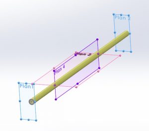
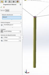
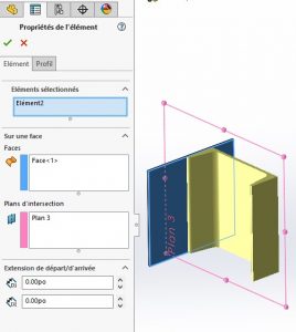
The new “Structure” function allows the creation of welded constructions in a different way. It is not necessary to draw a path for each profile. For example, it is possible to create a starting profile (“Primary Element”) from:
– From 4 planes;
– Of a path element (a bit like welded construction);
– By defining a length by selecting only one point (note the absence of a sketch in the requested selection);
– By defining an intersection between a face and a plane.
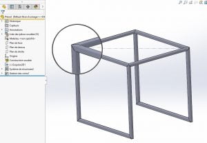
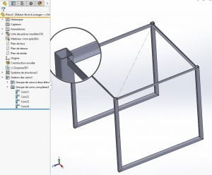
So, with a few clicks, you can define a structure, including corner treatment:
You can then modify the created structure (in one function!) to change the profiles of certain elements:
Following the creation of the external shape of the frame, reinforcements or other elements must generally be attached to it. As mentioned above, creation methods using entities other than sketch segments can be used. For so-called “secondary” elements, using the selection of two existing profiles, two methods are possible:
– Supporting Plan Element” uses an existing plan to position the newly created profile.
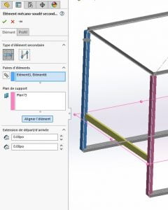
Activating chain selection allows the automatic creation of element pairs when two entities are selected.
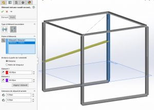
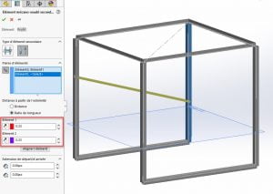
– Between point elements.
This method has two ways of working, using either distance or length ratio.
The first allows the definition of two distances from the starting point of the profiles:
We can see on the screenshot above that despite the two equally defined distances, the profile is at an angle. The reason for this is that the dimension is defined by the starting point of the profile, which corresponds to the starting point of the sketch, i.e. at the top of the structure for the profile on the left of the screenshot and at the bottom for the profile on the right:
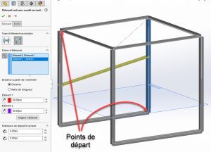
Just click on the appropriate icons to reverse the directions and thus obtain a secondary profile perpendicular to the primary profiles.
Ratios (whose value must vary between 0 and 1) of length relative to each previously selected element can also be used. In this way, always taking the direction into account, it is easy to create a spacer that would be on one side at the upper third of a profile and at the lower third on the other.
As for the creation of a drawing, the operation is the same as for a welded construction.
All in all, even if you are already using welded construction, this new working method can be confusing at first, but you quickly get used to it and learn to appreciate the lightness of the creation tree it produces. Moreover, just like the welded construction, the result produced is compatible with the BeamCutXperts beam optimization tool.
For more information visit our SOLIDWORKS product page, or consult an Xpert!


