Which Raise3D Solution Is Right for Your Industrial 3D Printing Needs?

BLOG

Which Raise3D Solution Is Right for Your Industrial 3D Printing Needs?

[techtips_featured_image_shortcode]

Over the past few years, 3D printing has evolved far beyond rapid prototyping. Today, it is widely used across industrial environments for tooling, functional parts, product development, supply chain optimization, and even end-use production.

However, as the technology has matured, however, one reality has become increasingly clear: there is no single 3D printing solution that fits every application.

From FDM and resin printing to polymer powder technologies, each platform offers different advantages in terms of precision, mechanical performance, production volume, and operating costs.

As a result, Raise3D has established itself as a compelling option for organizations seeking a balance between performance, accessibility, and versatility.

At Solidxperts, we help organizations evaluate, implement, and optimize these solutions as part of a broader additive manufacturing strategy. Raise3D is not a universal answer to every challenge; however, it often fits a wide range of industrial applications very well.

Raise3D Pro3 and Pro3 Plus: A Versatile Starting Point

For many organizations, adopting 3D printing begins with a straightforward objective: producing functional parts in-house without relying on external suppliers.

This is exactly where the Pro3 series excels.

The Raise3D Pro3 and Pro3 Plus are industrial FDM printers designed to support a broad range of applications, from functional prototyping to manufacturing jigs, fixtures, and production tooling. Their robust construction and dual-extrusion architecture provide the flexibility needed to tackle diverse projects with a single platform.
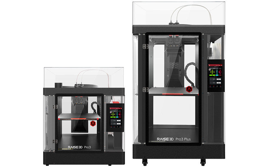
Raise3D Pro3 & Pro3 Plus

Build Volume

  • Pro3: 300 × 300 × 300 mm

  • Pro3 Plus: 300 × 300 × 605 mm

The extended build height of the Pro3 Plus is particularly valuable when producing large components or maximizing the number of parts manufactured in a single print job.

Compatible Materials

FDM technology supports a wide variety of thermoplastics, including:

  • PLA

  • PETG

  • ABS

  • ASA

  • TPU

  • Nylon

  • Fiber-reinforced composites

Raise3D also offers a portfolio of validated materials with optimized print profiles. This helps users achieve reliable and repeatable results with minimal setup.

Third-party materials can also be used when specific application requirements demand it. This flexibility is a major advantage, although official Raise3D materials typically provide the most predictable and repeatable performance in production environments.

Industries Served

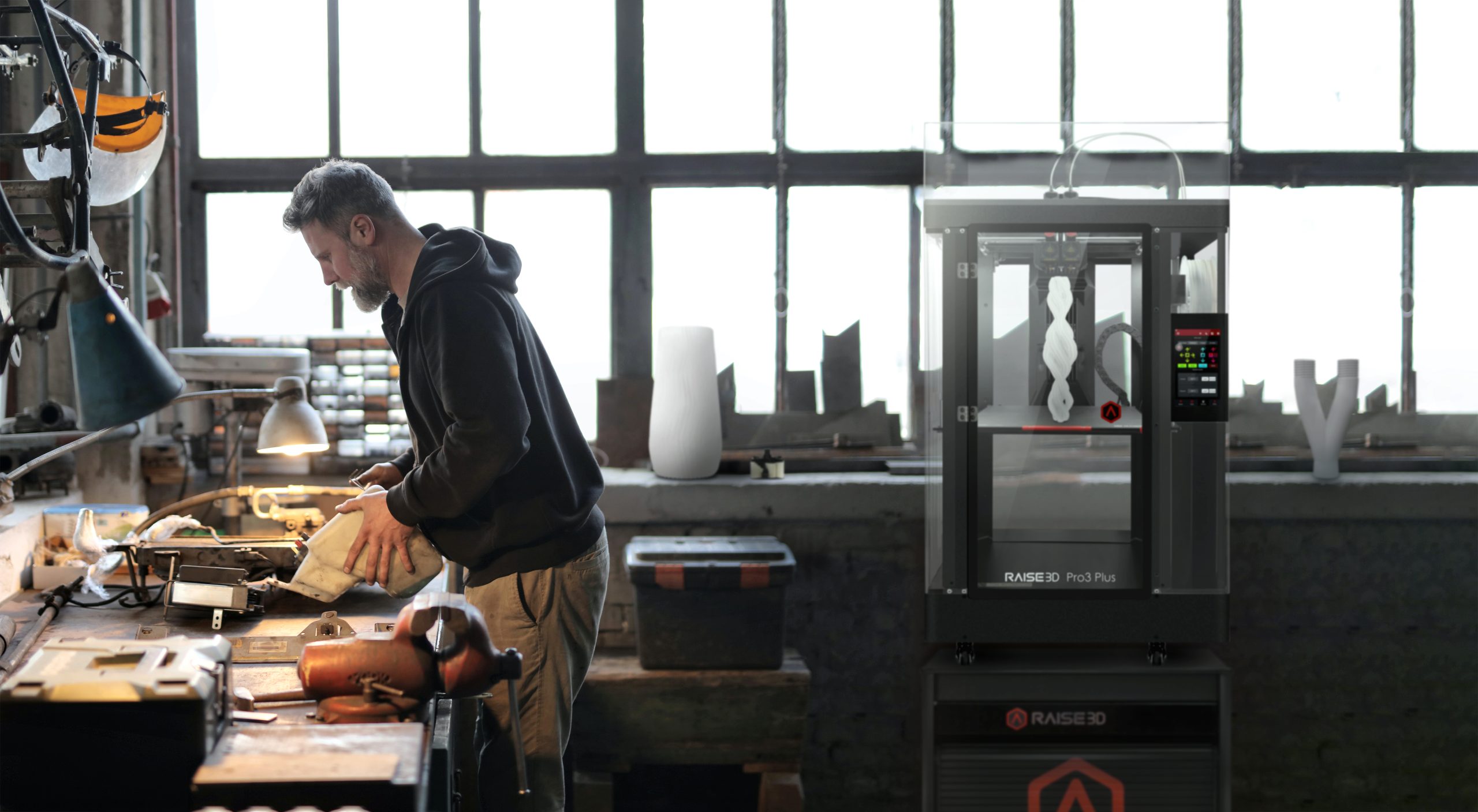
Manufacturing, automotive, aerospace, industrial design, and R&D teams all use the Pro3 series. Because of its versatility, organizations often rely on it when they want to support multiple applications without investing in several specialized machines.

Pro3 Series Industries

Why Is the Pro3 Series So Popular?

One of the greatest strengths of the Pro3 platform is its ability to grow alongside an organization’s needs. The same machine can be used to validate a prototype, manufacture an assembly fixture, or produce a replacement maintenance component. This versatility, combined with broad material compatibility and dependable performance, has made the Pro3 one of the most widely adopted industrial FDM platforms available today.

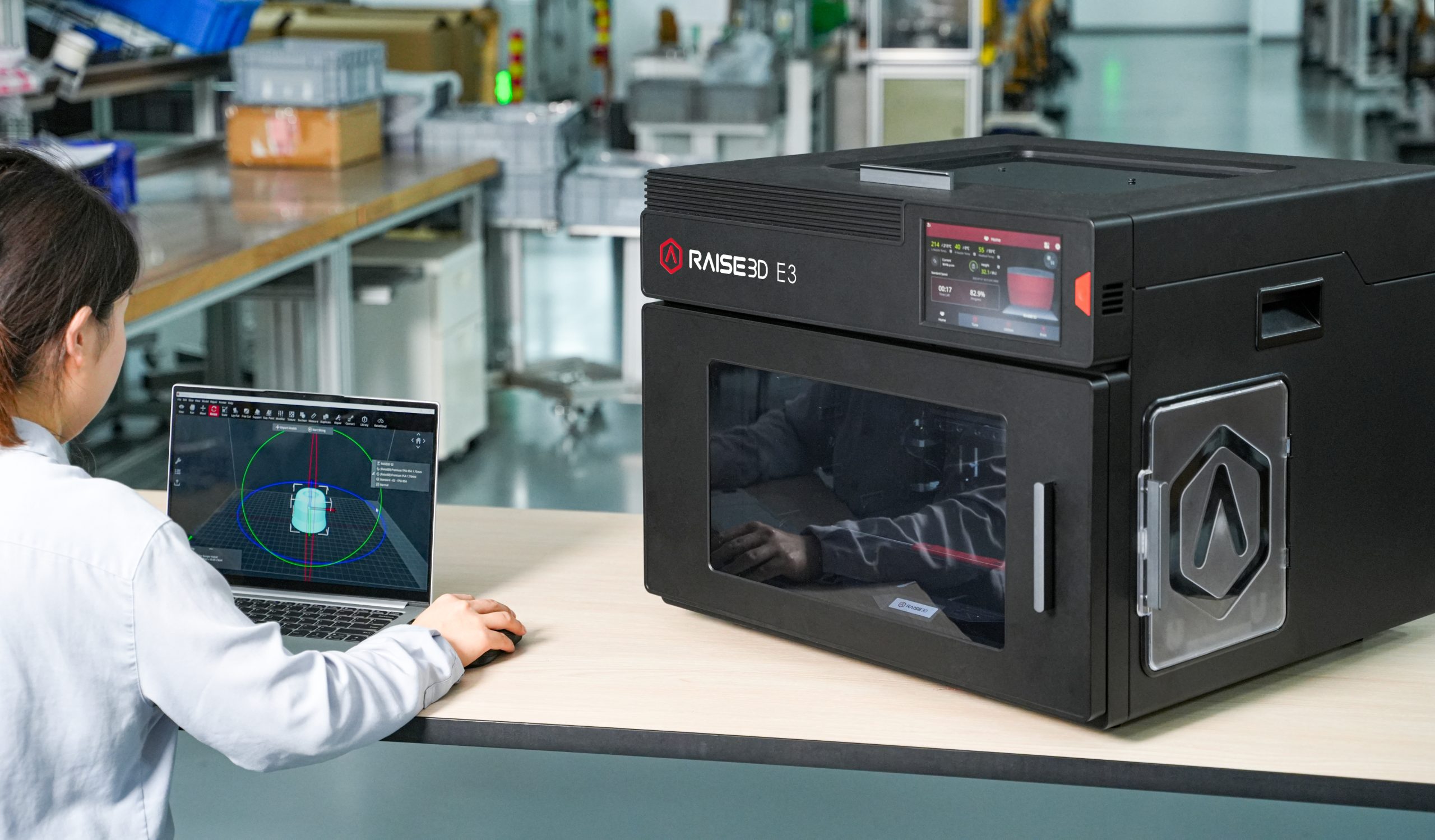
Raise3D E3: Productivity, Compactness, and Flexibility

Not every organization needs larger parts. In many cases, the primary goal is to improve efficiency or make 3D printing accessible to a broader range of users.

The Raise3D E3 was designed with this objective in mind.

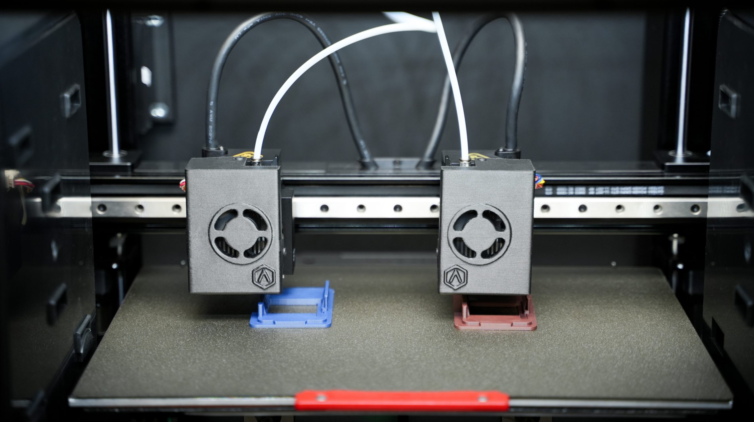
Built around an Independent Dual Extruder (IDEX) architecture, the E3 features two print heads that operate independently. This enables duplication and mirror-printing modes that can significantly increase productivity for certain applications.

Raise3D E3

Build Volume

330 × 240 × 240 mm

Compatible Materials

The E3 supports the major FDM material families:

  • PLA

  • PETG

  • ABS

  • ASA

  • TPU

  • Nylon

  • Engineering composites

Like other Raise3D platforms, official Raise3D materials benefit from optimized print profiles while still allowing users the freedom to work with third-party materials when required.

Industries and Environments

The E3 is particularly well suited for engineering departments, research centers, product development teams, and educational institutions. Its compact footprint and ease of integration make it an excellent choice for laboratories, classrooms, technical training centers, and office environments.

For organizations looking to expand access to 3D printing without deploying a dedicated production area, the E3 often represents an attractive and practical solution.

Raise3D E3 Industries

A Different Approach to Productivity

Rather than focusing on larger build volumes, the E3 improves efficiency by maximizing machine utilization. Its IDEX architecture enables simultaneous production of multiple parts or duplicate prototypes, naturally accelerating development cycles and reducing turnaround times for engineering teams.

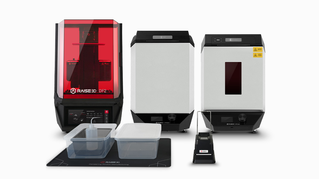
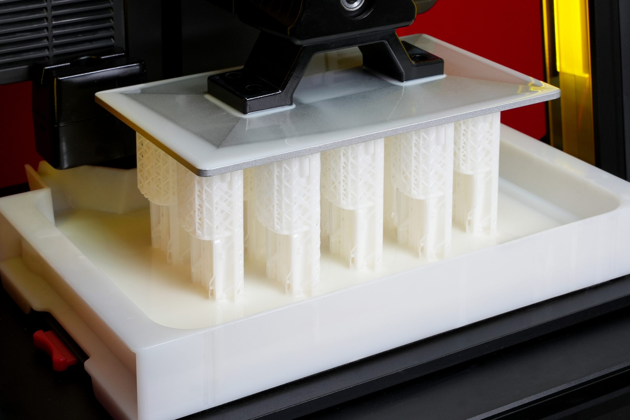
Raise3D DF2: When Precision Matters Most

Some applications demand a level of accuracy and surface quality that traditional FDM technologies cannot always achieve.

This is where the Raise3D DF2 stands out.

Powered by DLP technology, the DF2 delivers highly detailed parts with exceptional surface finish and excellent repeatability, making it ideal for applications where precision is critical.

Raise3D DF2

Build Volume

120 × 68 × 300 mm

Compatible Materials

The DF2 supports a range of photopolymer resins, including:

  • Rigid resins

  • Engineering resins

  • Flexible resins

  • Application-specific specialty resins

The DF2 ecosystem is built around validated materials and qualified process parameters, helping users achieve consistent results from one print to the next.

Industries Served

The DF2 is commonly used in medical, dental, industrial design, and research and development environments. It also supports specialized manufacturing applications where dimensional accuracy and surface quality are critical requirements.

One documented example is 3DPMolds, which uses the DF2 to accelerate the production of molds for low-volume plastic injection molding, demonstrating how resin technologies continue to expand into practical industrial applications.

A Platform Built for Accuracy

The DF2 is designed for organizations where surface finish, fine details, and dimensional precision play a central role in the manufacturing process. When these factors become critical, DLP technology offers advantages that are difficult to match with conventional FDM systems.

DF2 Scene

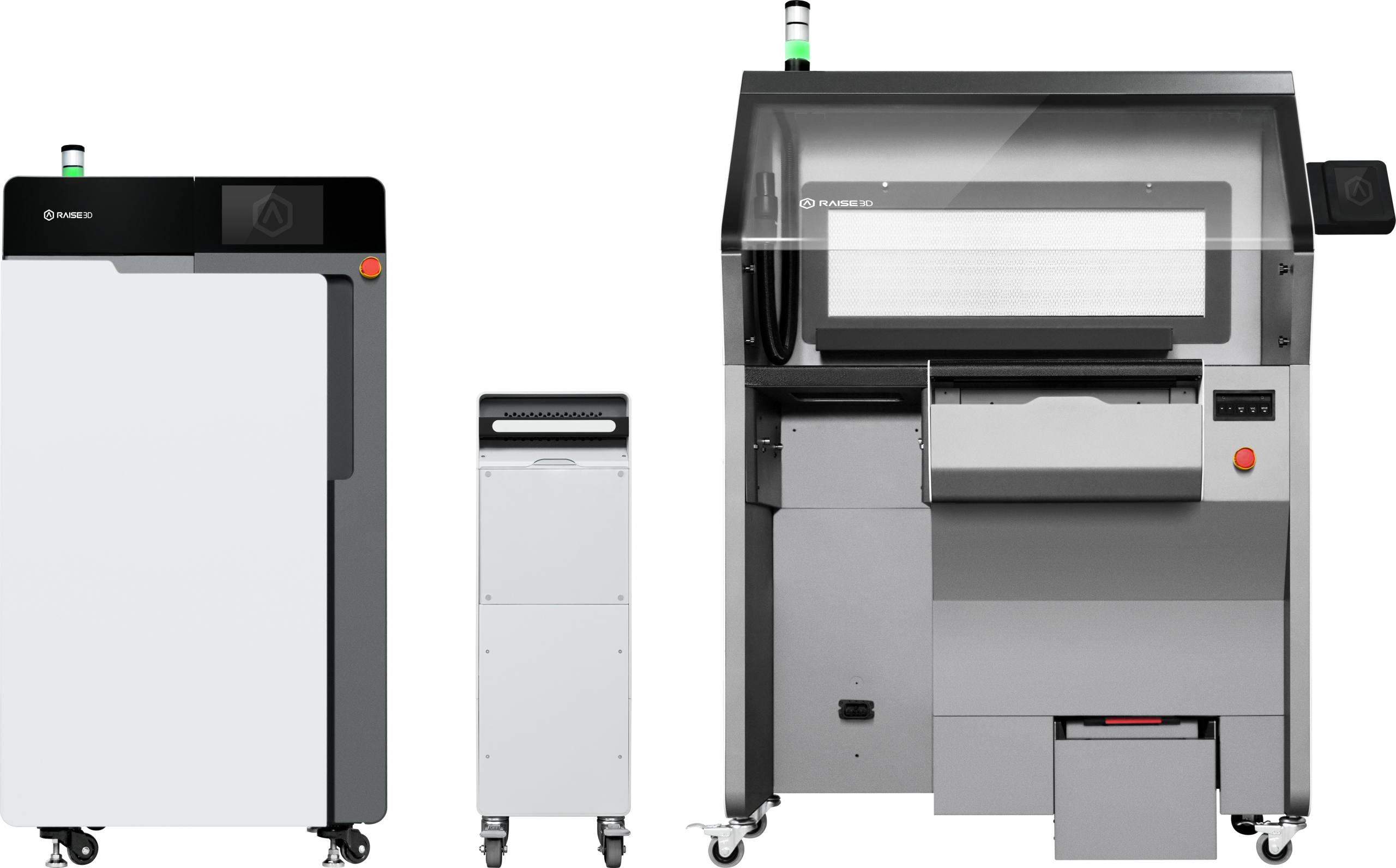
Raise3D RMS 220: Moving Toward Production

In some cases, additive manufacturing is no longer used simply to develop products, but to manufacture them directly.

The Raise3D RMS 220 was created for exactly this purpose.

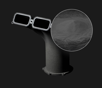
Based on Selective Laser Sintering (SLS) technology, the RMS 220 produces parts from polymer powder without the need for support structures. This enables greater design freedom and allows users to efficiently fill the build chamber with multiple parts in a single production cycle.

Raise3D RMS 220

Build Volume

220 × 220 × 350 mm

Compatible Materials

The RMS 220 is designed for industrial polymer powders such as:

  • PA11

  • PA12

Officially supported materials benefit from validated process parameters that help ensure repeatability and production stability.

Raise3D RMS 220 Compatible Materials

Industries Served

The RMS 220 is intended for manufacturers, automotive companies, aerospace organizations, and businesses looking to adopt additive manufacturing as a production technology.

Documented use cases include companies such as Kinboshi and LutraCAD, both of which have integrated the RMS 220 into industrial workflows involving the production of end-use and customized parts.

A Step Toward Manufacturing

SLS technology represents an important milestone in the adoption of additive manufacturing. The absence of support structures, combined with strong mechanical properties and exceptional design freedom, makes it particularly well suited for low- to medium-volume production.

Why Choose Solidxperts?

Selecting an industrial 3D printer involves much more than comparing technical specifications.

The real challenge is identifying the technology that will deliver the greatest value for your specific applications and business objectives.

At Solidxperts, we help organizations navigate this decision-making process. Our role extends beyond supplying equipment. We support our customers through needs analysis, technology selection, installation, training, and ongoing technical support.

This approach enables businesses to adopt additive manufacturing in a structured, scalable, and results driven manner.

What’s the Next Step?

With the Pro3 and Pro3 Plus, E3, DF2, and RMS 220, Raise3D offers a diverse portfolio of additive manufacturing solutions that address a wide range of industrial requirements.

Some organizations need a versatile platform to accelerate product development. Others require higher precision, greater design freedom, or increased production capabilities. Each technology serves a different purpose, and the application itself should always guide the decision.

One of Raise3D’s greatest strengths lies in its balance of performance, flexibility, and accessibility. These platforms enable organizations to integrate 3D printing into their operations without the complexity or investment often associated with more specialized technologies.

At Solidxperts, we believe a successful additive manufacturing project starts long before a machine is installed. It begins with a clear understanding of production goals, materials, operational constraints, and long-term business objectives.

Whether your goal is to accelerate prototyping, optimize production processes, or explore new manufacturing possibilities, our team is ready to help identify the technology best suited to your reality.

Because in industrial 3D printing, the best solution is not necessarily the most advanced one. It is the one that best meets your needs.

Looking to go further?


Lilian Beatrix

Additive Manufacturing Specialist

X_green_halo

Any questions? Need help? Ask one of our experts.

Whether you’re ready to get started or just have a few more questions, you can contact us toll-free:

    SOLIDWORKS Design vs Onshape: Which CAD Platform Is Right for Your Team?

    BLOG

    SOLIDWORKS Design vs Onshape: Which CAD Platform Is Right for Your Team?

    [techtips_featured_image_shortcode]

    Choosing a CAD platform is a bigger decision than just comparing modeling tools.

    Today, engineering teams need to think about collaboration, data management, cloud connectivity, licensing flexibility, training requirements, and even AI-powered productivity tools. Whether you’re replacing an older CAD system, evaluating cloud CAD for the first time, or planning for future growth, the platform you choose will impact your workflow for years.

    Two of the most common options being evaluated today are SOLIDWORKS Design and Onshape.

    Both are professional CAD solutions that support parametric modeling and offer cloud connected workflows. But they are built around very different philosophies.

    Let’s break down the differences.

    Quick Answer: SOLIDWORKS Design or Onshape?

    If your team wants a mature, industry-standard CAD platform with powerful desktop performance, extensive engineering tools, flexible licensing options, and access to the broader 3DEXPERIENCE ecosystem, SOLIDWORKS Design is typically the stronger choice.

    If your priority is a browser only CAD environment with simplified deployment and built-in cloud collaboration, Onshape may be worth considering.

    The right answer depends on your team’s workflows, product complexity, and long-term goals.

    What Is SOLIDWORKS Design?

    SOLIDWORKS Design is the latest evolution of the SOLIDWORKS portfolio.

    It combines the CAD environment engineers have trusted for decades with modern cloud services, collaboration tools, revision management, and AI-powered capabilities through the 3DEXPERIENCE platform.

    Today, organizations can choose between multiple deployment approaches:

    SOLIDWORKS Design Single-User License

    A named-user license connected directly to cloud services and the 3DEXPERIENCE platform.

    Benefits include:

    • Access from multiple devices

    • Built-in cloud collaboration

    • Cloud file and revision management

    • Continuous updates

    • AI-enabled cloud services and tools

    SOLIDWORKS Design Device License

    A machine-based license designed for organizations that prefer traditional deployment methods.

    Benefits include:

    • Local installation control

    • Machine-based activation

    • Multi-user workstation environments

    • Optional cloud connectivity

    • Support for controlled IT deployment strategies

    Both licensing options provide access to Cloud Services and future expansion into the broader 3DEXPERIENCE ecosystem.

    Comparison of SOLIDWORKS Design and Onshape interfaces to help teams choose the right CAD platform.SOLIDWORKS CAD Modeling Environment

    What Is Onshape?

    Onshape is a fully browser based CAD platform.

    Unlike traditional desktop CAD, there is no local installation. Users access their CAD environment through a web browser, and all data is stored in the cloud.

    Because the platform is cloud-native, Onshape provides:

    • Real time collaboration

    • Built-in version history

    • Browser based access

    • Automatic updates

    • Simplified IT deployment

    This makes it attractive for distributed teams, startups, educational institutions, and organizations looking to avoid workstation management.

    Side-by-side comparison of SOLIDWORKS and Onshape highlighting key features for engineering teams.

    Onshape CAD Modeling Environment

    SOLIDWORKS Design vs Onshape: The Biggest Differences

    Modeling Experience

    Both platforms use modern parametric modeling workflows.

    However, SOLIDWORKS Design still offers a more mature and feature rich modeling environment for many engineering use cases.

    Areas where SOLIDWORKS continues to excel include:

    • Large assemblies

    • Weldments

    • Routing

    • Drawings and detailing

    • Manufacturing documentation

    • Simulation integration

    • CAM integration

    • Advanced surfacing workflows

    For many engineers, SOLIDWORKS remains the benchmark for production ready mechanical design.

    Onshape delivers a modern modeling experience and continues to evolve rapidly, but some organizations transitioning from mature desktop CAD environments may find certain advanced workflows less developed.

    Performance

    This is where deployment philosophy matters.

    SOLIDWORKS Design

    Most CAD calculations happen locally on workstation hardware.

    Advantages:

    • Excellent performance on complex assemblies

    • Direct access to GPU resources

    • Better support for demanding engineering workloads

    • Less dependence on internet speed during modeling

    Onshape

    All modeling calculations occur on cloud infrastructure.

    Advantages:

    • Lower workstation requirements

    • Easy access from almost any device

    • Consistent performance across users

    For engineering teams working on large products, machinery, manufacturing equipment, or highly detailed assemblies, local workstation performance still offers significant advantages.

    Data Management

    Historically, data management was a major differentiator.

    Today, the gap is much smaller.

    Onshape

    Includes cloud-based data management by default.

    Users benefit from:

    • Version history

    • Branching workflows

    • Built-in collaboration

    • Cloud storage

    SOLIDWORKS Design

    Includes Cloud Services and can scale directly into the 3DEXPERIENCE platform.

    Organizations can start with:

    • Share and Markup

    • Store and Revise

    • Collaborative Spaces

    • Cloud revision management

    And later expand into:

    • Product lifecycle management (PLM)

    • Change actions

    • Governance workflows

    • Enterprise collaboration

    This creates a growth path from basic collaboration all the way to enterprise level product development.

    What About SOLIDWORKS xDesign?

    This is an important distinction that often gets overlooked.

    When comparing browser-based CAD, the most direct comparison is often SOLIDWORKS xDesign versus Onshape, not SOLIDWORKS Design versus Onshape.

    SOLIDWORKS xDesign is Dassault Systèmes’ cloud-native design solution, running entirely in a web browser with no local installation required. It combines modeling, collaboration, lifecycle management, and cloud storage directly within the 3DEXPERIENCE platform.

    Overview of SOLIDWORKS Design and Onshape showing differences in workflow and collaboration features.

    SOLIDWORKS xDesign Modeling Environment

    For organizations that like the flexibility of browser-based CAD but want to stay within the SOLIDWORKS ecosystem, xDesign is often worth evaluating alongside Onshape.

    Many companies ultimately adopt a hybrid strategy:

    • SOLIDWORKS Design for advanced mechanical design

    • SOLIDWORKS xDesign for cloud-native collaboration and conceptual work

    • 3DEXPERIENCE for data management and lifecycle control

    AI Features: SOLIDWORKS vs Onshape

    AI is becoming part of every CAD discussion, but it’s important to separate practical tools from marketing buzzwords.

    Neither platform has a “design my product” button.

    Instead, both focus on productivity improvements.

    AI in Onshape

    Onshape currently offers AI Advisor, an AI-powered assistant designed to answer questions and guide users through workflows using Onshape documentation and training resources as its knowledge base.

    AI Advisor can:

    • Answer workflow questions

    • Recommend best practices

    • Surface documentation

    • Provide troubleshooting guidance

    • Deliver contextual assistance inside the platform

    Importantly, Onshape states that AI Advisor does not currently generate designs or make engineering decisions.

    Visual comparison of SOLIDWORKS Design and Onshape focused on team collaboration and cloud capabilities.

    Onshape AI Advisor

    AI in SOLIDWORKS

    SOLIDWORKS has been expanding its AI roadmap aggressively through both desktop and cloud-connected tools.

    Recent AI capabilities include:

    • Auto-Generate Drawings

    • Command Predictor

    • Fastener Recognition

    • Assembly Performance Evaluator

    • Material Appearance Manager

    • BREP-to-Parametric CAD conversion

    • Design Change Impact analysis

    • PLM Model Insights

    • AURA AI Assistant

    Rather than acting as a documentation assistant, many of these tools directly interact with engineering workflows and CAD data.

    The goal isn’t replacing engineers. It’s reducing repetitive work, accelerating documentation, improving performance, and helping teams make decisions faster.

    Illustration comparing SOLIDWORKS Design and Onshape to help determine the best CAD solution for design teams.

    SOLIDWORKS AI Lab

    Which Platform Is Better for Growing Companies?

    This is often the most important question.

    For startups prioritizing fast deployment and simple browser access, Onshape can be an attractive option.

    For companies expecting growth, increasing product complexity, manufacturing integration, simulation requirements, or future PLM adoption, SOLIDWORKS Design often provides a more scalable path.

    One of the biggest advantages of the SOLIDWORKS ecosystem is that organizations don’t need to commit to everything on day one.

    You can start with:

    • SOLIDWORKS Design

    • Cloud Services

    • Basic collaboration

    Then gradually expand into:

    • PDM

    • PLM

    • Simulation

    • Manufacturing

    • Electrical

    • Cloud-native design

    • AI-driven workflows

    Without changing CAD platforms.

    Why work with Solidxperts?

    Choosing software is only part of the project.

    Implementation, training, data management strategy, and user adoption are often what determine whether a deployment succeeds.

    At Solidxperts, we work with organizations every day that are evaluating:

    • SOLIDWORKS Design

    • SOLIDWORKS xDesign

    • Cloud Services

    • 3DEXPERIENCE

    • PDM and PLM solutions

    • CAD migration projects

    Whether you’re moving from another CAD platform, modernizing your data management strategy, or exploring AI-enabled workflows, our team can help you build a roadmap that fits your reality not just a software brochure.

    The goal isn’t simply choosing a CAD tool.

    It’s building a design environment that will still make sense five years from now.

    Looking to go further?


    Michael Habrich

    3DEXPERIENCE Specialist

    X_green_halo

    Any questions? Need help? Ask one of our experts.

    Whether you’re ready to get started or just have a few more questions, you can contact us toll-free:

      Managing Roles on the 3DEXPERIENCE Platform

      BLOG

      Managing Roles on the 3DEXPERIENCE Platform

      [techtips_featured_image_shortcode]

      More and more organizations are moving to the 3DEXPERIENCE platform to streamline collaboration, improve data management, and connect their teams. One of the most important pieces of a successful rollout is understanding how Roles work, how they’re assigned, and how licensing is managed.

      In this article, we’ll walk through the full lifecycle of Role management, from inviting members to your tenant to assigning Roles individually or by group.

      Platform Administrator Access

      The steps outlined below require you to be a 3DEXPERIENCE Platform Administrator for your company tenant.

      If you don’t see the Platform Management or Members Management dashboards:

      • Reach out to your internal 3DEXPERIENCE administrator, or

      • If you are the admin and still can’t access them, contact your technical support team to help resolve the issue.

      Screenshot showing how to manage user roles and permissions on the 3DEXPERIENCE platform.

      Members Control Center

      Once you have the appropriate permissions, open the Members Control Center from:

      • The Members Management Dashboard, or

      • The Members tab within the Platform Management Dashboard

      This is your main workspace for:

      • Reviewing existing members

      • Viewing available Roles and license counts

      • Managing additional apps assigned to the tenant

      3DEXPERIENCE platform interface displaying tools for managing user roles, access rights, and responsibilities.

      Licensing Options (Before You Assign Roles)

      Before assigning any Roles, it’s a good idea to review the licensing behavior for your tenant.

      From the Members Control Center, select Configure Members Options.

      There are two key settings to review:

      1. License Expiration

      We strongly recommend enabling Automatically ungrant expired roles from members or groups.
      This ensures that:

      • Roles are automatically removed when licenses expire

      • Users don’t encounter access errors due to expired licensing

      2. Invitations from Administrators

      The option Allow administrators to grant roles without assigning automatically the associated license controls how external users access Roles:

      • Enabled: external users can use their own licenses

      • Disabled: licenses must come from your tenant

      Taking a moment to configure these options upfront can prevent licensing issues down the road.

      View of the 3DEXPERIENCE platform showing role configuration and assignment for team members.

      Understanding Member Role Assignments

      To see how these settings affect a specific user:

      1. Go back to Invite & Grant Roles

      2. Select Details for a member

      Each Role represents a purchased license and unlocks access to specific apps and capabilities.

      Key options include:

      Assign License:

      • Enabled → license is consumed from your tenant
      • Disabled → external user uses a license from another tenant

      Restrict Usage to the Platform:

      • Enabled → license can only be used on this tenant
      • Disabled → license can be used across tenants

      User management dashboard in the 3DEXPERIENCE platform used to assign, modify, and monitor platform roles.

      Assigning Roles to Members

      To assign Roles:

      1. Click View All to see every available Role

      2. Use search if needed, by Role name or trigram (for example, UES for Collaborative Designer for SOLIDWORKS)

      3. Set the licensing options for the Role

      4. Select the checkbox to grant it

      3DEXPERIENCE administration tools used to manage user roles and access permissions.

      If a Role requires prerequisites, you’ll be prompted to add them automatically. Simply confirm to proceed.

      3DEXPERIENCE platform screen illustrating the organization of user roles and permissions within a company.

      Inviting New Members

      Roles can also be assigned during the invitation process. You can invite users from:

      • My Platform Control Center

      Centralized management of user roles, licenses, and access permissions within the 3DEXPERIENCE environment.

      • Members Control Center

      3DEXPERIENCE administration interface used to define user roles, responsibilities, and access levels.

      Steps to Invite a Member:

      1. Click Invite Member

      2. Enter one or more email addresses

      3. Choose user rights:

      • Member
      • Tenant Administrator (always a good idea to have a backup admin)
      • External User

      4. Optionally include a personal message

      5. Click Next to select Roles

      User management on the 3DEXPERIENCE platform with role assignment and application access control.

      Choose the Roles to assign, review any prerequisite requirements, and configure licensing options if needed.

      3DEXPERIENCE administration panel showing user profile management and associated role configuration.

      In the final step, select any available apps and click Invite to complete the process.

      3DEXPERIENCE interface for user role management with options to assign and update permissions.

      Requesting Roles (User-Initiated)

      Users can also request Roles directly from the platform:

      1. Open the Compass

      2. Go to Company

      3DEXPERIENCE administration screen displaying a user list and their assigned roles configuration.

      3. Select a Role and click Request

      3DEXPERIENCE interface displaying role and access management settings for platform users.

      The administrator will receive both a platform notification and an email.

      Approving Role Requests:

      1. Open the Members Control Center

      2. Select Manage Requests

      3. Open the request tile

      3DEXPERIENCE configuration screen showing selection and assignment of user roles based on permissions.

      4. Click Accept to grant the Role

      3DEXPERIENCE administration interface showing user role management with filtering and assignment options.

      Assigning Roles Using Groups

      Groups are a powerful way to manage Roles at scale.

      Creating a User Group:

      1. Open the User Groups app (via the Compass)

      3DEXPERIENCE dashboard displaying available roles and their assignment to platform users.

      2. Click Create Group

      3DEXPERIENCE management screen showing role selection and customization of access rights for each user.

      3. Enter a name and description

      • Tip: name the group after the Role it will receive

      3DEXPERIENCE administration console for viewing, assigning, and managing user roles in a collaborative environment.

      4. Click Create

      5. Add members to the group and save

      3DEXPERIENCE interface showing user role management with search, filtering, and permission assignment options.

      Assigning Roles to a Group:

      1. Go to Members Control Center → Invite & Grant Roles

      2. Open Details for the desired Role

      3DEXPERIENCE interface displaying user role management with a preview of permissions associated with each role.

      3. Switch to the Groups tab

      4. Select the appropriate group and confirm any prerequisite Roles

      3DEXPERIENCE administration screen illustrating user role management and access rights structure within the platform.

      Any user added to the group will automatically receive the assigned Role.

      Removing Members from the Tenant

      When a user no longer needs access:

      1. Open the Members Control Center

      2. Select Details for the member

      3. Go to Settings

      4. Remove the user from the tenant

      3DEXPERIENCE user role management interface showing available roles and their assignment to organization members.

      Warning Make sure to remove any roles that have been assigned to that user before removing them from the platform to avoid any issues with future re-assignment.

      check mark button The best practice is to use User Groups to assign roles, that way you can simply remove a user from the User Group to remove their roles.

      Final Thoughts

      Managing Roles effectively is key to getting the most value from the 3DEXPERIENCE platform. With the right setup, you can ensure users have exactly the tools they need no more, no less while keeping licensing clean and manageable.

      Looking to go further?

      Your platform should work the way your team works and we’re here to help make that happen.


      Michael Habrich

      3DEXPERIENCE Specialist

      X_green_halo

      Any questions? Need help? Ask one of our experts.

      Whether you’re ready to get started or just have a few more questions, you can contact us toll-free:

        FAQ: AI at the Core of SOLIDWORKS and 3DEXPERIENCE

        BLOG

        FAQ: AI at the Core of SOLIDWORKS and 3DEXPERIENCE

        What is AI in SOLIDWORKS?

        At its core, SOLIDWORKS AI refers to a set of intelligent capabilities that assist engineers by automating repetitive tasks, providing design guidance, and enabling workflow orchestration through built-in features and Virtual Companions that can be interacted with using natural language.

        What AI features are currently available in SOLIDWORKS?

        Currently, available capabilities include automated drawing generation, general design assistance through an interactive chat interface, command prediction, sketch analysis and repair, fastener recognition, and many additional features that are being rapidly developed and expanded.

        Learn more about what’s available in SOLIDWORKS AI.

        Stay up to date with the latest SOLIDWORKS Design features.

        What is the difference between built-in AI features and Virtual Companions in SOLIDWORKS?

        On one hand, built-in AI refers to machine learning-based capabilities that enhance existing design workflows. On the other hand, Virtual Companions are AI assistants that can be engaged using natural language to access knowledge and perform specific tasks. Both built-in AI features and Virtual Companions are available directly within the SOLIDWORKS Design user interface.

        What are the roles of the new Virtual Companions?

        Unlike generic conversational agents, our companions embody AI at the heart of engineering, grounded in physics and causality.

        Name

        Specialty

        Example Application (E-Foil Wing)

        AURA

        Knowledge and Context

        Balances requirements for strength, lightweight construction, and water resistance (for example, choosing between carbon fiber and fiberglass).

        LEO

        Engineering Reasoning

        Optimizes the strength-to-weight ratio using carbon composites, specifically unidirectional carbon fiber with epoxy resin for stiffness and fatigue resistance.

        MARIE

        Materials Science

        Analyzes critical factors such as density (1.6 g/cm³), elastic modulus, and resistance to water-induced degradation.

        How do these entities collaborate to optimize a project?

        Innovation emerges from the combination of multiple perspectives. AURA explores the range of possibilities, MARIE grounds the project in rigorous materials science, and LEO ensures mechanical and manufacturing feasibility. Together, they help identify the optimal technical solution without compromising safety or manufacturability.

        Why is the move to the Cloud essential for these new AI capabilities?

        Knowledge extraction, deep data mining, and the execution of complex AI models require significant computing power. Cloud infrastructure is the only practical way to provide these resources flexibly and cost-effectively to organizations of all sizes.

        Does SOLIDWORKS AI use customer data for training?

        No. Customer data is not used to train AI models. Governance controls ensure the protection of intellectual property. You can learn more by visiting the 3DS Trust Center.

        Can AI automatically create drawings?

        Yes. SOLIDWORKS Design includes the ability to automatically generate 2D drawings by interacting with Virtual Companions using natural language. Drawings can be created according to specified standards, templates, and dimensioning schemes, helping accelerate the documentation process.

        Can AI automate repetitive CAD tasks?

        Yes. SOLIDWORKS AI automates repetitive engineering tasks such as drawing creation and assembly structure generation. Additional capabilities will continue to be introduced in future releases.

        How does SOLIDWORKS AI protect intellectual property?

        SOLIDWORKS AI ensures that customer intellectual property remains isolated and secure. Learn more about the specific security protocols by visiting the 3DS Trust Center.

        How do I get started with AI in SOLIDWORKS?

        Start by exploring the built-in AI capabilities and current Virtual Companion features available through the AI Lab task pane directly within SOLIDWORKS Design. Access to Virtual Companions requires Cloud Services to be enabled, which are included with every SOLIDWORKS Design license.

        Can AI automatically fix CAD models?

        AI can identify issues, explain errors, and suggest corrections. However, engineers remain responsible for reviewing and approving any modifications.

        Will AI replace CAD designers and engineers?

        No. AI helps automate repetitive tasks and uncover valuable insights, but engineers remain responsible for design intent, validation, and decision-making.

        Want to Learn More?

        Discover more tips and tutorials on our YouTube channel.

        Explore best practices with our experts.

        Or contact our team, we’re here to help you get the most out of your platform.


        Benoit Bilodeau

        Senior Solutions Architect

        X_green_halo

        Vous avez des questions ? Besoin d’aide ? Demandez à l’un de nos experts.

        Que vous soyez prêt à commencer ou que vous ayez quelques questions supplémentaires, vous pouvez nous contacter sans frais :

          Exporting Derived Outputs from the 3DEXPERIENCE Platform

          BLOG

          Exporting Derived Outputs from the 3DEXPERIENCE Platform

          [techtips_featured_image_shortcode]

          On the 3DEXPERIENCE platform, Derived Outputs such as PDFs, DXFs, STEP files, and other neutral formats are created from your CAD data for downstream use. These files are often shared with customers, suppliers, or partners who don’t have access to your platform tenant.

          In this article, we’ll walk through a few practical ways to package and export Derived Outputs so they’re ready to send outside your organization.

          Note: Dassault Systèmes provides general documentation on Derived Outputs. If you need help with setup, automation, or best practices, our technical support and implementation teams are always happy to help.

          Choosing the Right Method

          There are a couple of different apps and workflows you can use, each with its own advantages depending on:

          • The number of files involved

          • Whether you’re working with a single assembly or many

          • How much cleanup you want to do afterward

          Let’s take a look at the most common approaches.

          Using the Product Explorer App

          Method 1: Download Derived Outputs from a Single Assembly

          1. Open the assembly in Product Explorer that already has Derived Outputs.

          2. Select the top-level assembly node (it will highlight in blue).

          User exporting derived output files from the 3DEXPERIENCE Platform interface.

          3. Click the Information (i) icon in the lower toolbar.

          Derived outputs including PDF, DXF, and STEP files displayed within the 3DEXPERIENCE Platform.

          This opens the information side panel.

          4. Navigate to Derived Formats.

          Engineer preparing CAD-derived files for external sharing using the 3DEXPERIENCE Platform.

          5. Click Download All Derived Outputs.

          Export settings window for derived outputs on the 3DEXPERIENCE Platform.

          6. Choose which 2D and 3D formats you want to include.

          7. Name the ZIP file and click Download.

          Downloading multiple derived outputs from the 3DEXPERIENCE Platform in a packaged folder.

          If you’ve added multiple assemblies to Product Explorer, you’ll need to repeat this process for each one.

          Trade-off:

          • ✔ Clean output (Derived Outputs only)

          • ✖ One assembly at a time

          Method 2: Export Multiple Assemblies at Once

          If you need to collect outputs from several assemblies or even unrelated parts, this method is much faster.

          1. Add assemblies or parts to Product Explorer.

          2. Select multiple items using checkboxes or Shift + Select.

          3. Click Export As from the bottom toolbar.

          Example of neutral CAD file formats generated from SOLIDWORKS data in 3DEXPERIENCE

          4. Name the export, enable Expand All, and set the Derived Format Options.

          5. Click Export.

          Collaboration workflow using exported derived outputs from the 3DEXPERIENCE Platform.

          A background job will start.

          Once complete:

          • A notification appears in the upper-right corner.

          User selecting derived output files for export from a project dashboard in 3DEXPERIENCE.
          • Click the notification to open the CAD Data Processor Monitoring app.

          • Use the Download button to retrieve the ZIP file.

          Exported PDF and STEP files ready for downstream manufacturing and review.

          This ZIP will include both CAD files and Derived Outputs. To keep only the outputs, simply open the ZIP in Windows Explorer, sort by file type, and remove any files you don’t need.

          Trade-off:

          • ✔ Multiple assemblies or mixed files at once

          • ✖ Manual cleanup required

          Using the Bookmark Editor App

          Method 1: Download Outputs from a Single Assembly

          1. Locate the assembly in a bookmark (or add it to one).

          2. Right-click the assembly and choose Information, or open the side panel

          3. In the window or side panel, navigate to Derived Outputs.

          4. Click Download All Derived Outputs.

          Packaging derived outputs into a ZIP archive from the 3DEXPERIENCE Platform.

          This workflow mirrors the single-assembly method in Product Explorer.

          Trade-off:

          • ✔ Simple and clean

          • ✖ One assembly at a time

          Method 2: Export Multiple Items from a Bookmark

          This method works the same way as the multi-selection approach in Product Explorer.

          1. Add all required assemblies or parts to a bookmark.

          2. Select the files you want.

          3. Click Export As from the upper toolbar.

          Digital workflow illustrating the transfer of derived outputs from CAD to external stakeholders.

          4. Configure the Derived Format options and start the export.

          As before, the resulting ZIP will include CAD data along with the Derived Outputs, so some cleanup may be required.

          Trade-off:

          • ✔ Ideal for large batches or mixed content

          • ✖ Requires removing CAD files afterward

          Final Thoughts

          Whether you’re sending a single PDF or packaging dozens of STEP and DXF files, the 3DEXPERIENCE platform gives you flexible ways to get the right data out securely and efficiently.

          The key is choosing the method that best fits your situation:

          • Single assembly, clean output → Download All Derived Outputs

          • Multiple files, faster packaging → Export As

          Looking to go further?

          • Check out more tips and tutorials on our YouTube channel.

          • Explore best practices with our experts.

          • Or reach out to your Solidxperts team we’re here to help you get the most out of your platform.


          Michael Habrich

          3DEXPERIENCE Specialist

          X_green_halo

          Any questions? Need help? Ask one of our experts.

          Whether you’re ready to get started or just have a few more questions, you can contact us toll-free:

            3DDrive vs. 3DSpace: What’s the Difference?

            BLOG

            3DDrive vs. 3DSpace: What’s the Difference?

            [techtips_featured_image_shortcode]

            The 3DEXPERIENCE platform includes a powerful set of tools designed to support collaborative product development. Two of the most commonly used apps for storing and managing files are 3DDrive and 3DSpace.

            At first glance, they can look similar, but they’re built for very different purposes. Understanding how each one is meant to be used will help your team work more efficiently and avoid confusion down the road.

            What Is 3DDrive?

            Think of 3DDrive as the 3DEXPERIENCE equivalent of tools like Dropbox or OneDrive.

            3DDrive allows you to:

            • Store and access files from anywhere

            • Edit and collaborate on documents in real time

            • Share files easily, including with external users

            • Integrate with other cloud storage services

            You’ll find 3DDrive under My Apps in the 3DEXPERIENCE platform, and it’s also accessible directly inside SOLIDWORKS.

            3DDrive interface in the 3DEXPERIENCE platform for cloud file sharing and management

            3DDrive uses a familiar folder based structure and focuses on flexibility and convenience. It’s a great choice for:

            • General file sharing

            • Early-stage collaboration

            • Working with customers, suppliers, or partners outside your organization

            What it doesn’t include is built-in product data management there’s no revision control, lifecycle states, or formal approval process.

            3DDrive interface in the 3DEXPERIENCE platform for cloud file sharing and management

            What Is 3DSpace?

            3DSpace is built for teams that need structure, control, and traceability.

            3DSpace interface in the 3DEXPERIENCE platform for product data management and revision control

            Instead of simple folders, 3DSpace is organized around Collaborative Spaces, where teams work together on shared project data. Within 3DSpace, you can:

            • Control access and permissions

            • Track revisions and history

            • Assign maturity states like In Work and Released

            • Lock files to prevent conflicting edits

            These capabilities make 3DSpace a strong foundation for PLM-driven workflows, including:

            • Engineering change processes

            • Approval workflows

            • Long-term product data management

            3DSpace is ideal for engineering teams that need confidence in version control and data integrity.

            3DSpace interface in the 3DEXPERIENCE platform for product data management and revision control

            3DDrive vs. 3DSpace: Which Should You Use?

            The short answer: it depends on how you work.

            • 3DDrive is best when:

              • You need fast, flexible file sharing

              • You collaborate frequently with external users

              • You want a familiar, lightweight cloud storage experience

            • 3DSpace is best when:

              • You need controlled access and revision tracking

              • Your team is ready for PLM-style workflows

              • Data accuracy, traceability, and approvals matter

            The good news is that both apps integrate directly with SOLIDWORKS, so you can access the right tool without leaving your design environment.

            Comparison between 3DDrive and 3DSpace in 3DEXPERIENCE showing file sharing and product data management

            Final Thoughts

            3DDrive and 3DSpace aren’t competing tools. They’re complementary. Many teams start with 3DDrive for simple collaboration and gradually introduce 3DSpace as their data management needs grow.

            Not sure which approach makes the most sense for your team? That’s where we come in.


            Michael Habrich

            3DEXPERIENCE Specialist

            X_green_halo

            Any questions? Need help? Ask one of our experts.

            Whether you’re ready to get started or just have a few more questions, you can contact us toll-free:

              AI in SOLIDWORKS: What’s New in FD02

              BLOG

              AI in SOLIDWORKS: What’s New in FD02

              [techtips_featured_image_shortcode]

              From Features to Assistants: A Shift in How You Work

              With the SOLIDWORKS 2026 FD02 update, AI is starting to feel less like a set of isolated tools, and more like an integrated part of your workflow.

              This release introduces two major concepts:

              • AI Virtual Companions (prompt-driven interaction)

              • Contextual Performance Assistants (proactive recommendations)

              Together, they represent a shift toward software that doesn’t just respond, but actively supports your decisions in real time.

              Let’s break down what’s new and what it actually means for your day-to-day work.

              A New Direction: AI That “Thinks Alongside You”

              Up until now, most AI features in CAD have been reactive:

              • You click a command

              • The software executes

              FD02 starts moving beyond that.

              Instead, SOLIDWORKS is introducing AI that:

              • Understands context

              • Responds to natural language

              • Flags issues before they become problems

              👉 The goal isn’t automation for its own sake
              👉 It’s reducing friction in engineering workflows

              AI Virtual Companion: Working with Prompts

              One of the biggest changes in FD02 is the expansion of the AI Virtual Companion.

              This is a text-based interface inside SOLIDWORKS where you can:

              • Ask questions

              • Request actions

              • Get insights about your model

              What’s New in FD02:

              Design Change Impact

              You can now ask:

              “What happens if I change this feature?”

              The AI will:

              • Scan the model

              • Identify affected parts and assemblies

              • Highlight downstream dependencies

              • Indicate who or what may be impacted

              Why It Matters:

              This allows you to evaluate risk before making changes, instead of reacting after something breaks.

              SOLIDWORKS 2026 FD02 interface showing AI-powered change impact analysis on a mechanical assembly model.

              Auto-Generate Drawings (Beta) – Now Prompt-Driven

              Auto-Generate Drawings gets a major upgrade.

              What’s New:

              • Direct access to the Drawing Creation AI skill

              • Ability to customize outputs using natural language prompts

              You can now:

              • Adjust drawing tables

              • Refine views

              • Modify layout behavior

              Why It Matters:

              You move from:

              “Generate → manually fix everything”

              to:

              “Generate → guide the result intelligently”

              SOLIDWORKS 2026 FD02 showing AI-assisted drawing creation with a conversational interface generating and saving technical drawings automatically.

              Material Appearance Manager (Beta)

              What’s New:

              Using simple prompts, you can:

              • Apply material appearances

              • Update visuals across assemblies

              • Maintain consistency automatically

              Why It Matters:

              It removes repetitive cleanup work and improves visual standardization, especially in larger assemblies.

              SOLIDWORKS 2026 FD02 interface showing AI-assisted material appearance assignment on a mechanical assembly using natural language prompts.

              Contextual Performance Assistants: Proactive Help

              The second major innovation in FD02 is the introduction of always-on performance assistants.

              Instead of waiting for you to troubleshoot, these tools:
              👉 Monitor your work in real time
              👉 Flag issues as they appear
              👉 Recommend fixes immediately

              You’ll typically see these as contextual prompts or purple notifications in the interface.

              Fastener Simplification

              When inserting detailed fasteners (like threaded hardware):

              The assistant will:

              • Detect performance-heavy geometry

              • Explain the impact

              • Offer to suppress threads automatically

              Why It Matters:

              This is a perfect example of AI preventing problems before they slow you down.

              SOLIDWORKS 2026 FD02 Performance Assistant warning users about detailed threaded fasteners and recommending automatic geometry simplification to improve assembly performance.

              Assembly Performance Evaluator (Beta)

              What’s New:

              You can now:

              • Ask questions about assembly performance

              • Receive AI-generated diagnostics

              • Get targeted recommendations

              Why It Matters:

              Large assemblies are complex to troubleshoot manually.

              This tool turns:

              Trial-and-error debugging

              into:

              Guided, data-driven optimization

              SOLIDWORKS 2026 FD02 showing AI-driven assembly performance evaluation with diagnostics and recommendations for optimizing large assemblies.

              AI-Driven Modeling: Fixing a Longstanding Problem

              BREP to Parametric CAD (Beta)

              This is one of the most impactful additions in FD02.

              What’s New:

              AI converts:

              • STEP

              • IGES

              into:

              • Fully editable, feature-based SOLIDWORKS models

              Why It Matters:

              You can:

              • Modify imported geometry

              • Avoid rebuilding parts from scratch

              • Work faster with supplier or legacy data

              This directly addresses one of the biggest inefficiencies in CAD workflows.

              SOLIDWORKS 2026 FD02 converting imported geometry into a fully editable parametric CAD model using AI-driven feature recognition.

              AI Beyond CAD: Data and Governance:

              FD02 also expands AI into data management and PLM workflows.

              PLM Model Insights

              You can query:

              • Revision history

              • Ownership

              • Maturity state

              • Related files

              Using natural language.

              SOLIDWORKS 2026 FD02 showing AI-powered PLM model insights with revision history and lifecycle data accessed through natural language queries.

              Governance Automation (Beta):

              Includes:

              • Auto Task Creation

              • Create PLM Change Action

              Why It Matters:

              AI is now helping manage:

              • Workflows

              • Approvals

              • Change processes

              Not just geometry.

              SOLIDWORKS 2026 FD02 showing AI-assisted project planning and automatic task creation within a PLM workflow interface.

              A Clear Trend: From Tools to Teammates:

              Looking at FD02 as a whole, the direction is clear.

              AI in SOLIDWORKS is evolving toward:

              • Conversational interaction (ask instead of search)

              • Proactive assistance (alerts instead of errors)

              • Automation of repetitive tasks

              • Better visibility into design and data

              This isn’t about replacing engineers.

              It’s about:
              👉 Reducing manual overhead
              👉 Improving decision-making
              👉 Keeping workflows moving

              What You Need to Access These Features:

              To use most AI functionality in FD02, you’ll need:

              • SOLIDWORKS 2026 (FD02 or newer)

              • Access to the 3DEXPERIENCE platform

              • Proper roles (e.g., Collaborative Designer for SOLIDWORKS)

              • Active cloud connectivity

              Need help? Follow our guide on how to get started with AI in SOLIDWORKS:
              Guide: Getting Started with AI in SOLIDWORKS

              Should You Start Using AI in FD02?

              Yes, but with a clear strategy.

              Start with:

              • Assembly Performance Evaluator

              • Auto-Generate Drawings

              Then explore:

              • BREP to Parametric CAD

              • Design Change Impact

              Keep in mind:

              • Many features are Beta

              • Outputs should always be validated

              • AI is an assistant, not a decision-maker

              AI Is Becoming Embedded

              FD02 marks an important shift as we move from standalone AI features to integrated, workflow-aware intelligence. But the biggest change is not necessarily what AI can do. It’s how naturally it fits into the way engineers already work every day.


              Michael Habrich

              3DEXPERIENCE Specialist

              X_green_halo

              Any questions? Need help? Ask one of our experts.

              Whether you’re ready to get started or just have a few more questions, you can contact us toll-free:

                How SOLIDWORKS AI Is Being Positioned by Manish Kumar

                BLOG

                How SOLIDWORKS AI Is Being Positioned by Manish Kumar

                [techtips_featured_image_shortcode]

                The Future of Work: Shifting from Automation to Value Creation

                In the age of AI, I am often asked: What is the true nature of “value”? For engineers, the pressure to reduce costs and optimize workflows is constant. Historically, we turned to simple task automation. Today, AI is shifting the focus from merely speeding up repetitive tasks to amplifying human ingenuity.

                Redefining Value in Engineering

                What is the real value of an engineer? It isn’t clicking a mouse to create a sketch; it is problem-solving and innovation.

                Consider a visit to the doctor. Is a doctor’s value found in typing notes into a chart, or in the focused diagnosis and long-term health planning they provide? Today, many doctors use specialized AI companions to handle transcription, allowing them to give patients their undivided attention.

                Similarly, an engineer’s value lies in ideation and rapidly converting concepts into virtual twins for experimentation. The manual steps—the clicks to create geometry—are a means to an end. While some fear AI will take away the “enjoyable” parts of CAD, we must ask: do you enjoy the manual execution, or the creative breakthrough? Automating the “busy work” of drawing creation lets us return to the reason we became engineers in the first place: creative problem-solving.

                The Human Role in an AI-Driven Future

                A common concern is that AI will replace human oversight. I strongly disagree. When designing a turbine blade or an aircraft engine, human validation is critical—lives depend on it.

                AI acts as a multiplier, not a replacement. If an engineer produces one design today, AI might help them produce ten tomorrow. This actually increases human responsibility. Engineers must review more outputs, ensure regulatory compliance, and make higher-level decisions. AI expands our capabilities, but it does not originate ideas. Just as AI image generators require a human prompt and refined intent, 3D CAD will always require human direction.

                This is the democratization of design. Thirty years ago, SOLIDWORKS brought CAD to every desktop, democratizing 3D CAD. Today, AI is the next wave of that movement, making 3D modeling accessible so more people can solve massive, complex problems.

                Embracing the Multiplier

                As I said at 3DEXPERIENCE World in February: AI is the engine; you are the driver.

                Professionals should never underestimate their worth. AI is a tool to unlock your potential, and the gap between early adopters and those who resist will only continue to grow. Learning to make AI work for you is the key to staying at the forefront of the innovation revolution.

                So, I ask you: which of your tasks could be delegated to agentic AI, or virtual companions, to help you better showcase your true value? I look forward to hearing from you and seeing what our future holds.

                X_green_halo

                Any questions? Need help? Ask one of our experts.

                Whether you’re ready to get started or just have a few more questions, you can contact us toll-free:

                  Why SOLIDWORKS Is Leading the AI Revolution in CAD

                  BLOG

                  Why SOLIDWORKS Is Leading the AI Revolution in CAD

                  [techtips_featured_image_shortcode]

                   SOLIDWORKS and its parent company, Dassault Systems, have been ahead of the competition when it comes to all things AI. SOLIDWORKS started developing AI features, also known as Smart Features, decades ago, giving their software a lead above the competition. While continuing to invest and stay ahead of the pack, all new AI assistants are now directly available within the application, ensuring that integration is seamless.

                  Follow along in this blog, because I want to show you all the amazing features SOLIDWORKS has already implemented over the year, along with what is in store for the future. By the end, I will have shown how the recent attempts of our competition’s software do not hold a candle to the advances SOLIDWORKS has already made, let alone what is in store for the future.

                  Past Additions of Machine Learning and Artificial Intelligence

                  For over a decade, SOLIDWORKS has been continuously adding features that make use of machine learning and artificial intelligence. From features such as Smart Mates or Smart Fasteners to new AI Drawing Creation, SOLIDWORKS has been working to optimize engineer time, and reduce the number of tedious repetitive tasks.

                  Excelling in time optimization for years, SOLIDWORKS has continued making tools designed with engineering resources in mind. Tools like Fully Defined Sketch and Selection Accelerators have been available for years, helping make the sketching and selection processes faster. Always improving, SOLIDWORKS took the predictive selection accelerator from the Fillet command, and added it into Chamfers in recent years, making seamless group selection even easier than before in both features.

                  Machine Learning and Artificial Intelligence

                  Users can go from this underdefined sketch to this fully defined sketch in 3 quick clicks!

                  Machine Learning and Artificial Intelligence 2

                  There have even been productivity increasing tools in the assembly environment for just as long! Smart Fasteners and Smart Mates have allowed engineers to snap together parts and fill their holes with fasteners for over a decade. Even before the general public heard about AI and chatbots, SOLIDWORKS has been working to implement AI based features to improve the engineering experience.

                  Current SOLIDWORKS AI Tool Additions

                  In 2026, SOLIDWORKS continues this trend of improving the engineering experience through implementing countless new features in the most recent as well as future updates. Some such features include AI Drawing Creation, AI Assembly Creation, Automatic Fastener Recognition, Command Predictor, and Pattern Assistant, to name a few. With these tools, SOLIDWORKS will become even smarter, and can predict an engineer’s next move; whether that move is dropping a nut into place, or needing to add a pattern of bolts in one swift movement. SOLIDWORKS can now even assist engineers in making sure the most efficient patterning methods are being used, as an efficiency check to young engineers.

                  SOLIDWORKS AI Tool Additions

                  Tools, like Automatic Fastener Recognition, make use of a database of thousands of fastener files, allowing the SOLIDWORKS AI to determine if a part is a fastener as soon as it is dragged in to your current project. This recognition will allow the system to offer better mate conditions and groupings, for instance pairing a new nut to your existing bolt.

                  Additionally, features like AI Drawing Creation and AI Assembly Creation take processes out of the engineers hands and begin these processes in the system background before bringing the engineer in for confirmation. From laying out standard views and annotations, to organizing folder structures in assemblies, SOLIDWORKS continues to assist in simplifying and standardizing these initial steps in creation and documentation.

                  SOLIDWORKS AI Tool Additions

                  With the use of SOLIDWORKS AI Drawing Creation, a simple conversation with LEO about the desired settings and defaults leads to a drawing created faster than ever before!

                  SOLIDWORKS AI Tool Additions

                  Addition of AI assistants in SOLIDWORKS

                  SOLIDWORKS AI Assistants

                  The most recent additions of artificial intelligence to SOLIDWORKS include the three all new AI assistants; AURA, LEO, and MARIE. Each serves a unique role throughout the CAD Design process, as described below.

                  AURA is the starting point of any great project, even before you draw your first sketch. AURA holds the ability to leverage knowledge from both web and enterprise sources, making it your one stop shop for rapid confirmation. For questions regarding basic design rules and suggestions, or even searching your company’s knowledge base, AURA can answer it all.

                  After the first steps with AURA are completed, LEO takes the reins. LEO can help users effectively solve many complications through the design process, helping validate your design and optimize your processes. Throughout both mechanical design, as well as simulation, LEO can take your prompts to generate assembly structures, as parametric features, run studies, and even help resolve design errors. For both answering questions, and offering solutions, LEO can solve many engineering headaches.

                  The last assistant in the lineup is MARIE, your scientific research specialist. With expertise in materials science, chemistry and more, your thorough scientific research can be simplified. With this third member of the SOLIDWORKS AI trifecta, you have an assistant in your corner for every part of the engineering design process.

                  Competitors attempts at replication

                  Outside of SOLIDWORKS, many competitors have tried their hand in implementing AI for the benefit of users. While many companies have had good feature additions in recent years, it is hard to compare them to the decades of experience and additions seen in SOLIDWORKS. The following sections detail some of these features within the competing software, and shows how SOLIDWORKS has taken the lead in all things AI.

                  For starters, Autodesk has invested in AI in Fusion 360. However, you will find no such features in Inventor. Looking into these, features like CAM hole recognition have existed in SOLIDWORKS for some time. The drawing AI tool seems to be in the early stages, having very little interaction or flexibility. Fusion can add relationships and dimensions automatically, much like Fully Define Sketch (something that has existed in SOLIDWORKS for nearly 20 years). The main hurdle that Autodesk will have to overcome is that their files don’t talk to each other, unlike the fully associative files found in SOLIDWORKS, making their AI feature development harder.

                  Other competitors like Siemens have three main enhancements, Magnetic Snap, Automated Drawings, and a design copilot, all things that have existed or do now exist in SOLIDWORKS. Lastly, Onshape has a lot of potential due to their cloud-based nature, however the content released as of now is just in the infancy stage.

                  The Bottom Line: SOLIDWORKS AI is Changing the Game

                  After looking at the history of feature development, as well as a brief look at the competition, you can see that SOLIDWORKS continues to be designed with the engineer in mind. From features that increase productivity by decreasing repetition, to tools that give you a head start in the design process, SOLIDWORKS is a lifesaver. Many competitors’ Artificial Intelligence ambitions are just beginning, so SOLIDWORKS is working hard to maintain the lead they already have, while pushing engineering design technology to the next level. Our SOLIDWORKS Technical Team has been ahead of the pack when it comes to learning and using AI, so please contact us with any questions, and find out what makes us the Solidxperts.


                  Alain

                  Alain Provost

                  Senior Technical Sales Executive

                  X_green_halo

                  Any questions? Need help? Ask one of our experts.

                  Whether you’re ready to get started or just have a few more questions, you can contact us toll-free:

                    Resolving issues with part name display in eDrawings compared to SOLIDWORKS

                    BLOG

                    Resolving issues with part name display in eDrawings compared to SOLIDWORKS

                    [techtips_featured_image_shortcode]

                    It is quite common for information shared with the workshop through eDrawings not to appear exactly as expected. In fact, part names may seem incorrect, incomplete, or simply different from what the engineering team sees in SOLIDWORKS.

                    As a result, this is a question we are regularly asked: “Why are part names not the same in eDrawings as in the SOLIDWORKS assembly?”

                    So, if you use eDrawings as a viewer for shop floor personnel, this article is for you. Let’s take a few minutes to understand why this happens and more importantly, how to fix it in a sustainable way.

                    The Typical Context: eDrawings as a Workshop Support Tool

                    In many manufacturing companies, eDrawings is used to:

                    • View assemblies without a SOLIDWORKS license;

                    • Visualize complete machines on the shop floor;

                    • Quickly identify parts to manufacture or assemble;

                    • Reduce paper drawings.

                    It is an excellent tool as long as the displayed information is clear and consistent.

                    However, in some cases, workshop users are faced with:

                    • Cryptic file names;

                    • Internal references that are not meaningful;

                    • Part names different from those used by engineering.

                    A Key Point to Understand: eDrawings Does Not Interpret, It Displays

                    First of all, it is important thing to clarify: eDrawings does not “guess” anything. It simply displays the information coming from SOLIDWORKS, based on the assembly structure, the properties defined on each part, and the export options used. Therefore, if the display does not meet your expectations, it is almost never an eDrawings bug, but rather a source data or configuration issue.

                    The Three Most Common Causes

                    In practice, three main causes explain this behavior:

                    1. The displayed name is the file name, not the business designation

                    By default, eDrawings often displays the part file name (.SLDPRT) instead of:

                    • The business designation;

                    • The part number;

                    • The workshop-oriented description.

                    Example: PLT_4587_V3.SLDPRT instead of Conveyor support plate – 10 mm steel

                    For the shop floor, the added value is… very limited.

                    2. Custom properties are not being leveraged

                    Additionally, in SOLIDWORKS, you most likely already have:

                    • Description

                    • Part Number

                    • Internal reference

                    • Customer name

                    But if these properties are not filled in consistently or eDrawings is not configured to display them, they become useless for the workshop.


                    3. The eDrawings export process is not standardized

                    Finally, an export performed quickly, by different users and without a clear procedure often results in:

                    • inconsistent displays;

                    • different habits from one project to another.

                    As a result, the workshop gradually loses confidence in the tool.

                    Recommended Best Practice: Think “Workshop” Directly in SOLIDWORKS

                    In reality, the solution is not in eDrawings…it starts in SOLIDWORKS.

                    Here is a simple and effective approach:

                    Use a workshop-oriented property

                    For example:

                    • Description

                    • or Workshop_Description

                    This property should be clear, readable and free of unnecessary CAD jargon.

                    Standardize how properties are filled in

                    Apply the same logic to all parts:

                    • same property name

                    • same text convention

                    • same language

                    Ultimately, this is a small effort on the engineering side…but delivers significant gains on the production side.


                    Structuring the eDrawings Export for the Workshop

                    To ensure consistency, the eDrawings export should:

                    • always come from an up-to-date assembly;

                    • follow a simple, documented procedure;

                    • display useful information, not technical noise.

                    This is exactly why a short internal procedure is often an excellent idea.

                    eDrawings: An Excellent Tool, When Properly Prepared

                    eDrawings is neither a design tool nor a PDM system. It is a technical communication tool.

                    In other words, like any communication, quality depends on what is sent, not only on the tool itself.

                    As a result, when best practices are in place the workshop gains autonomy, the unnecessary questions decrease, and the interpretation errors are reduced.

                    From Confusion to Clarity: Making eDrawings Work for the Workshop

                    If part names displayed in eDrawings do not match what you expect, know that you are not alone, it is not inevitable, and it is almost never a bug. More often than not, it is an opportunity to review how information is prepared and transferred to the workshop.

                    Very often…a few simple adjustments are enough to turn eDrawings into a true production support tool.

                    FAQ

                    Why do part names in eDrawings differ from those in SOLIDWORKS?

                    eDrawings displays information coming from SOLIDWORKS files, typically the file name or custom properties. If these data are not standardized or workshop-oriented, the display may appear inconsistent.

                    Is this an eDrawings bug or limitation?

                    No. In most cases, the issue lies in how data is structured upstream in SOLIDWORKS, not in eDrawings itself.

                    What is the best practice to display clear part names on the shop floor?

                    Use a dedicated, readable SOLIDWORKS property such as Description or Workshop_Description, filled consistently across all parts.

                    Is a SOLIDWORKS license required on the shop floor?

                    No. eDrawings allows assembly viewing without a SOLIDWORKS license, making it a cost-effective solution for workshop use.

                    What is the tangible benefit for the company?

                    A clear and standardized eDrawings display helps to:

                    • reduce interruptions between engineering and production

                    • limit interpretation errors

                    • improve overall operational efficiency


                    Alain

                    Alain Provost

                    Senior Technical Sales Executive

                    X_green_halo

                    Any questions? Need help? Ask one of our experts.

                    Whether you’re ready to get started or just have a few more questions, you can contact us toll-free:

                        Download

                          Download

                            Download