SOLIDWORKS is an indispensable tool for engineers and designers across various industries. One standout feature that elevates SOLIDWORKS to new heights is its Simulation module. This powerful tool enables users to analyze and validate their designs before physical prototypes are created, ultimately saving time and resources while ensuring optimal product performance. In this blog, we will delve into the capabilities and benefits of SOLIDWORKS Simulation, shedding light on how it empowers engineers to bring their innovative ideas to life.
Understanding SOLIDWORKS Simulation
SOLIDWORKS Simulation is a robust finite element analysis (FEA) tool integrated seamlessly into the SOLIDWORKS CAD environment. It allows engineers to subject their designs to virtual testing, simulating real-world conditions and scenarios. This simulation-driven design approach empowers users to make informed decisions early in the design process, leading to better product performance, reduced development costs, and faster time-to-market.
Key Features of SOLIDWORKS Simulation:
Structural Analysis
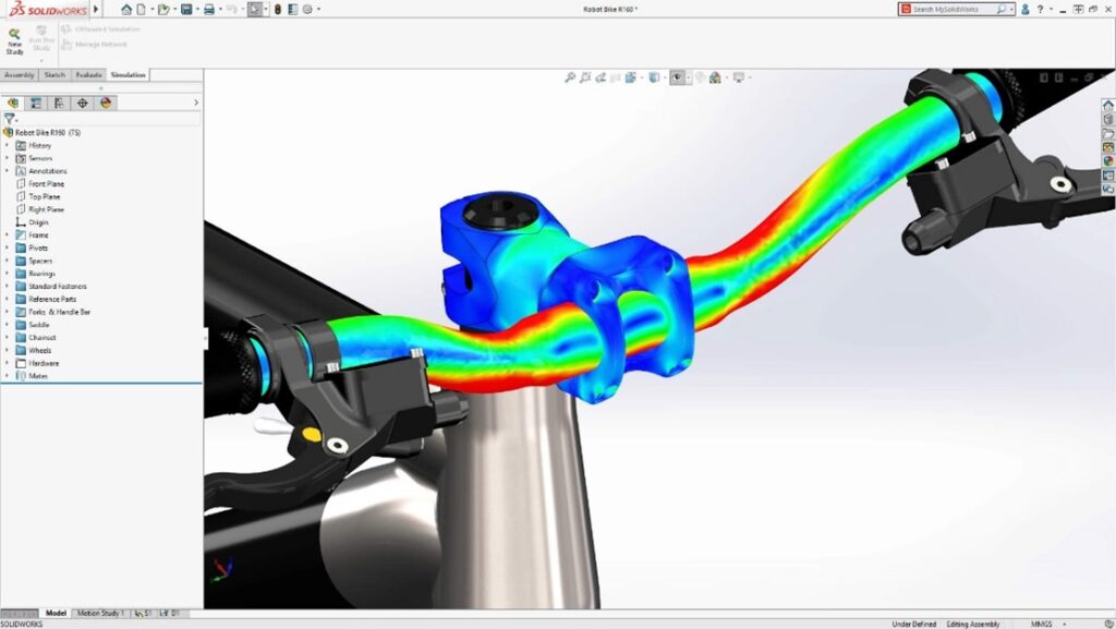
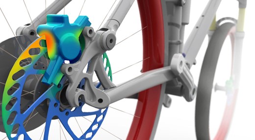
SOLIDWORKS Simulation provides a comprehensive suite of tools for structural analysis, allowing engineers to evaluate the effects of loads, forces, and vibrations on their designs. Whether it’s a simple static analysis or a complex dynamic simulation, this feature helps ensure that components can withstand real-world conditions.
Thermal Analysis
Thermal management is crucial in many engineering applications. SOLIDWORKS Simulation allows users to simulate heat transfer and thermal behavior within their designs. This capability is particularly beneficial for optimizing electronic components, ensuring they operate within acceptable temperature ranges.
Fluid Flow Simulation
For products that involve fluid dynamics, such as pumps, valves, or HVAC systems, SOLIDWORKS Simulation provides a fluid flow analysis tool. Engineers can visualize and analyze how liquids or gases move through their designs, enabling them to optimize performance and efficiency.
Motion Analysis
Understanding the motion of mechanical components is essential in designing machinery and mechanisms. SOLIDWORKS Simulation offers motion analysis tools that help engineers simulate and validate the movement of assemblies, ensuring proper functionality and performance.
Benefits of Using SOLIDWORKS Simulation:
Reduced Prototyping Costs
By virtually testing designs, engineers can identify and rectify potential issues before physical prototypes are created. This significantly reduces the need for costly iterations and prototyping, saving both time and resources.
Improved Product Performance
Simulation allows for a deep understanding of how a design will behave under various conditions. This insight enables engineers to optimize designs for maximum performance and reliability.
Faster Time-to-Market
The ability to perform thorough virtual testing expedites the design validation process. Engineers can make informed decisions early in the development cycle, accelerating the overall product development timeline.
Enhanced Innovation
SOLIDWORKS Simulation encourages a more iterative and innovative design process. Engineers can experiment with different concepts, knowing that they can quickly assess their viability through simulation before committing to a specific design direction.
SOLIDWORKS Simulation is a game-changer for engineers, providing a virtual testing ground that empowers them to create better, more reliable products. By seamlessly integrating simulation into the design process, SOLIDWORKS enables engineers to push the boundaries of innovation while ensuring the practicality and performance of their designs. Whether it’s structural analysis, thermal simulation, fluid flow analysis, or motion analysis, SOLIDWORKS Simulation is a versatile tool that unlocks a world of possibilities for engineers seeking to bring their creative visions to life.
To learn more about SOLIDWORKS Simulation visit our webpage, Click Here.
To reach out to an Xpert for more information or to start taking advantage of our Simulation solutions, Click Here.

Any questions? Need help? Ask one of our experts.
Whether you’re ready to get started or just have a few more questions, you can contact us toll-free: