Industry Tags: Industrial
How to create a multi-body sheet metal part from a solid geometry

The sheet-metal module included in SolidWorks allows us to create different types of consumer products that are part of our daily lives.
Continue reading “How to create a multi-body sheet metal part from a solid geometry”
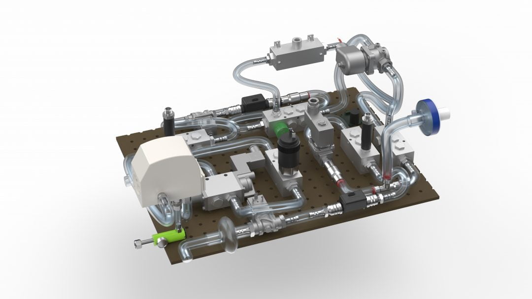
Welded Constructions with the SOLIDWORKS Structure System

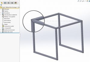
From the 2004 version of SOLIDWORKS onward, the welded construction function speeds up the creation of assemblies because it allows the representation of assemblies without having to create multiple individual files. But, there is more since version 2019.
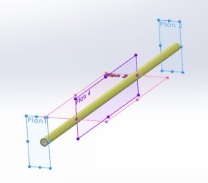
The new “Structure” function allows the creation of welded constructions in a different way. It is not necessary to draw a path for each profile. For example, it is possible to create a starting profile (“Primary Element”) from:
– From 4 planes;
– Of a path element (a bit like welded construction);
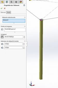
– By defining a length by selecting only one point (note the absence of a sketch in the requested selection);
– By defining an intersection between a face and a plane.

So, with a few clicks, you can define a structure, including corner treatment:
You can then modify the created structure (in one function!) to change the profiles of certain elements:
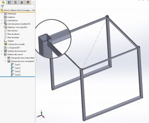
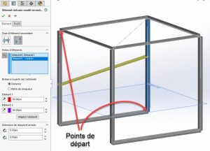
Following the creation of the external shape of the frame, reinforcements or other elements must generally be attached to it. As mentioned above, creation methods using entities other than sketch segments can be used. For so-called “secondary” elements, using the selection of two existing profiles, two methods are possible:
– Supporting Plan Element” uses an existing plan to position the newly created profile.
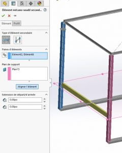
Activating chain selection allows the automatic creation of element pairs when two entities are selected.
– Between point elements.
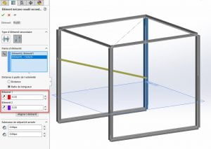
This method has two ways of working, using either distance or length ratio.
The first allows the definition of two distances from the starting point of the profiles:
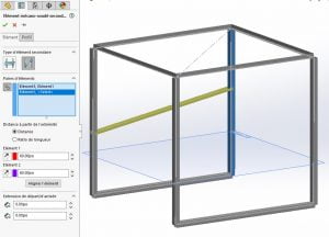
We can see on the screenshot above that despite the two equally defined distances, the profile is at an angle. The reason for this is that the dimension is defined by the starting point of the profile, which corresponds to the starting point of the sketch, i.e. at the top of the structure for the profile on the left of the screenshot and at the bottom for the profile on the right:
Just click on the appropriate icons to reverse the directions and thus obtain a secondary profile perpendicular to the primary profiles.
Ratios (whose value must vary between 0 and 1) of length relative to each previously selected element can also be used. In this way, always taking the direction into account, it is easy to create a spacer that would be on one side at the upper third of a profile and at the lower third on the other.
As for the creation of a drawing, the operation is the same as for a welded construction.
All in all, even if you are already using welded construction, this new working method can be confusing at first, but you quickly get used to it and learn to appreciate the lightness of the creation tree it produces. Moreover, just like the welded construction, the result produced is compatible with the BeamCutXperts beam optimization tool.
For more information visit our SOLIDWORKS product page, or consult an Xpert!

Any questions? Need help? Ask one of our experts.
Whether you’re ready to get started or just have a few more questions, you can contact us toll-free:
3D modeling for additive manufacturing
Repair Resolution –
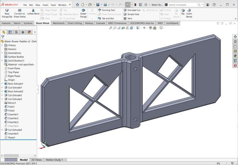
You might be an engineer – if, you fix broken fitness equipment with CAD and 3D printing. This case study shows just how that was done. It starts with a budget water rower exercise machine that had arm failures in the resistance paddle which spins inside the water tank. The machine had been purchased early in the year and the paddle arms failed by December.
Note that the arms of the original paddle broke off where the plastic transitions from a thinner beam profile to the larger hub. Of course, it could have been predicted by using SOLIDWORKS Flow, Plastics, or Simulation software, but that discussion will be saved for another article.
For the moment we will focus on designing and producing a 3D printed replacement paddle that is more similar to the design used in expensive health club water rower machines.
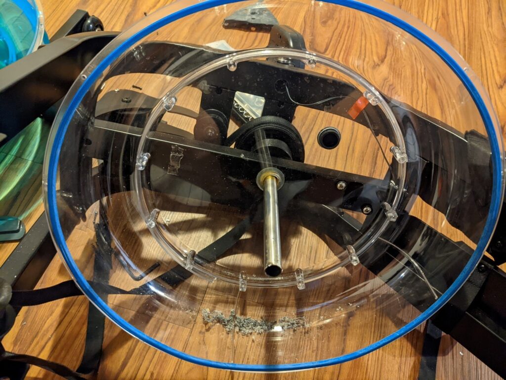
The commercial grade water rower has single mixing paddle design that extends across the diameter of the tank. There are openings between the shaft hub and the scoop ends, but the paddle has solid plastic arms at the top and bottom of the water tank. The budget rower was connected only at the bottom of the water tank leading to increasing offset dynamic loads as athlete exertion increases.
Although the original design paddle diameter of 18 inches is larger than many 3D printer print volume dimensions, it was possible to get 16 inches diagonally across the build plate. Adjusting the width of the working portion of the paddle and having the solid section on top allows the surface area displacing the water to be similar between the 3D printed design and the injection molded paddle.
By using a pattern of triangle and diamond shapes for the open section, the replacement paddle can be printed without support.Chamfers are used for edge breaks around the edges and openings for better flow characteristics while still being easy to print.
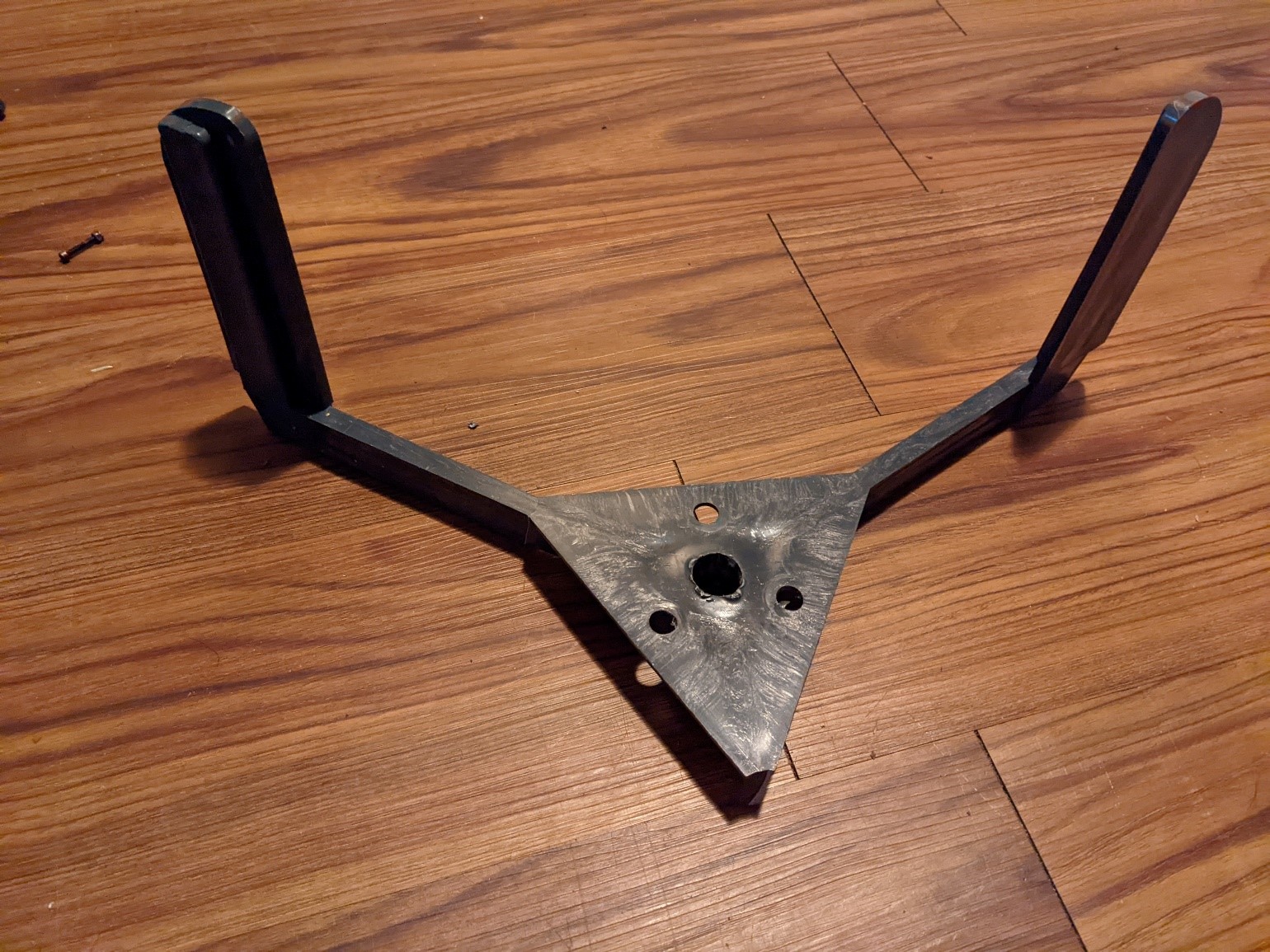
The original paddle had a pressed and brazed connection between the paddle and rower shaft, and this has been replaced with a pentagon shaped hole to allow for screw fastening to the shaft.
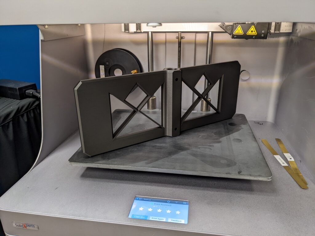
For strength Markforged Onyx filament is used which is a carbon and nylon blend. The wall passes are increased and gyroid infill is used along with maintaining the full paddle width through the paddle cross section.
Disassembly of the original paddle from the rower was a bit involved, requiring drilling and a gear puller to get the shaft clear to accept the printed replacement.
Some additional drilling and bolting allowed the new paddle to be installed on the rower shaft.
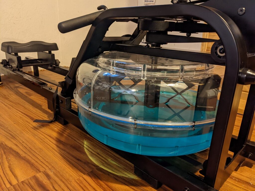
With a slight adjustment of water volume in the tank, the 3D printed replacement paddle provides the same resistance and workout as the when the machine was new.
Water flow is different with the replacement paddle but the workout is the same. And the repair is done in time for a new year of health resolutions.
John Nolin
Senior Applications Engineer
SolidXperts

Any questions? Need help? Ask one of our experts.
Whether you’re ready to get started or just have a few more questions, you can contact us toll-free:
What’s New SOLIDWORKS 2022 – Hit List

Installation –
Admin Image types (option) Standard, Remote, Compressed
Remote – allows users to download image from internet / SOLIDWORKS Customer Portal instead of from company VPN
Compressed – smaller download, but must use full package at each service pack upgrade
SOLIDWORKS Electrical – new client or server specific installation options (easier for multi-user environments)
PDM – vault views can now be deployed as part of an Admin Image
Copy Settings wizardcan now adapt to System Options distributed and locked with Admin Image
User Interface –
New message bar pop-up at top of graphics window
Quick Copy utility for Measure tool – allows 1 click copy of values or values + units
Command Search now integrated in Shortcut toolbar (and can be directly added to toolbar)
Drawings saved to PDF can now include the sheet / paper color
Reference Geometry display and selection during Mate, Measure or Pattern.
While in the command hover mouse over faces or cylinders press [Q] to momentarily display reference geometry for selection.
Additional options for Component Tree display to show various combinations of Component Name, Description, Configuration, and Display State.
Sketching –
Linear sketch entity is now usable for direction reference in patterns
Sketch textnow works in patterns
Parts –
Coordinate systems – can be set with exact values in 3D space (independent of a geometry reference to select)
Coordinate systems – can be referenced or selected by its origin, an axis or plane
Cosmetic Threads – better display, retains proper depth and edge attachment
Draft Across Parting Lines – now draft can be applied in both directions from a parting line as 1 feature
External Threaded Stud Wizard – an extension of detailed Thread Feature that builds the stud with threads at 1 time
Hole Wizard Slots – dimension to arc center option added, hit [Tab] to rotate 90deg while placing feature.
Hybrid Modeling – allows mesh bodies (after BREP conversion) to be edited with surface features and combined with solid features
Segmented Mesh bodies – converted mesh bodies can have faces turned into classic BREP
Mirror about 2 planes – with 1 feature creation
Rotate Section View– around a hole or axis
Thickness Analysis – now offers Resolution control with Low, Med, High tessellation sizes
Model Display –
Performance improvement for 3D textures and silhouette edges
Sheet Metal –
Edge flanges on curves can now apply edit profile to limit the feature extents
Etched contours on bends (sketch text or split lines) retain display in flattened state
Structure System & Weldments –
Structure Systems now supports end caps
Custom Properties of older version weldments (2017 or earlier) can be upgraded to newer property architecture
Improvements in Complex Corner property manager
Ability for multiple secondary members (using between points, or up to member methods)
Connector Elements for Structure Systems now supported
Can include cut features as connector is placed.
ImprovedCustom Properties dialog for Structure Systems and Weldments bodies
Assemblies –
(x) Automatically optimize resolved mode, hide lightweight mode
Improves performance by letting system control lightweight use behind the scenes (behaves as resolved to the user)
Open Subassemblies in Different Mode– right click option to load subassembly as LDR or Resolved (independent of upper assembly current mode)
Exclude from BOM – custom configuration property for components
Configuration Table – Design Table functionality without needing the embedded Excel sheet (file size / performance / no excel ???)
Section View – option toexclude failed componentsand still create section view
Assemblies and components with equations will auto resolveas needed, if loaded lightweight
Move with Triad– automatically appears when more than 1 component selected
AdditionalQuick Mates options on In Context Toolbar
Detailing & Drawings –
Alternate Position Viewsnow allow cropping
Predefined Drawing Viewsnow support trimetric, dimetric, or flat pattern types
Detailing Modeimprovements – available for any version file, Save model data and include standard views performance options added
Geometric Tolerance frames now build dynamically on screen
Radius / Diameter dimension display toggle now on incontext bar for easier access
Sheet Metal flat pattern views can now show bend lines when sketch display is hidden
Handling of detailed cut lists within BOMtables is improved
Symmetric Linear Diameter Dimension is added
Import / Export –
Performance improvements forimport of large DXF/DWG and STEP files
Ability to select specific IFC Entity types from the files for import
Assigned colors of entities properly support in DXF/DWG export
PDM –
Improvements with Windows AD integration: additional user data fields, profile import, login validation tools
Improved configuration property managementand control
Archive Server and User log export capabilities added
Preview Tab now shows full eDrawings viewer controls
Performance improvementsfor file operations even when database has higher latency
Manage –
UI improvements for BOM, Project Properties, Process Tab and more
Additional user rights controls over check out of items
Replace User capability added
Performance improvements for BOM and Project display as well as PDM check in/out
Blended Curvature Based Mesher is now default for new studies
Bonded and Contactperformance improvements
Improved solver performance and automatic solver selection
Tools to set camera perspective to matchbackplate
Shadow catcher property can be assigned to scene elements
Scenes Tab UI improvements
Animations improvements for motion studies, key frames and more
Render Output Viewer – in project viewing, control, and management of renders
Pattern Tool – replaces and improves prior Formation function (Vee, Circle, Scatter, Grid)
CAM –
Toolpath endpointscan be set for a custom color for easier viewing
Filter for Mill & Turn tools containing specified text string
Composer –
Ability to import SOLIDWORKS appearance decals
Import file versionextensions: ACIS up to 2021 , Creo 7, SOLIDWORKS 2022
Electrical –
Links in BOM cells – allows multiple items to reference 1 mfg part
PDF data file support for Project PDF exports (bind PDF function)
Multiple UI improvements
Attribute capability added to Origin & Destination arrows (shows mark of connected component)
Electrical Content Portalcan now be set as dockable panel in UI
Improved Connection Point creation
Inspection –
New API– auto open SOLIDWORKS files, Balloon drawings, create reports and more
Standalone now supportsall native SOLIDWORKS files and NX/Unigraphics *.prt files (MBE)
Smart Extract in standalone has improved recognition and parsing of PDF file content
MBD –
HTML(5) exportoption on 3D PDF creation
Angle Dimension manual annotation for DimXpert added
Geometric Tolerancingimprovement including ANSI Y14.5 or ISO 1101 release selection
Support for SOLIDWORKS custom file properties when saved as eDrawings files
Components list UIimprovements
Scene Plot utility – stores all displayed plots and model display
Compare Tool improvements
Range Function – for handling of transient effects (such as power derating due to temperature calculation)
Flux Plot – now available within Transient Explorer
Plastics –
Symmetric & Cyclic Cavity and Runner Layout tools
Injection Location Advisor – based on part geometry software selects up to 4 recommended injection locations
Polymer materials data updates (using latest manufacturer properties)
SABIC, Polyplastics, Solvay Specialty Polymers, Radici Group, LANXESS
Improved UI of Plastics Manager Tree
4K and higher displayresolution support
Solver performance improvement – cooling calculation time reduced 34%, Fill & Pack reduced 60%
Routing –
Flatten Routeimprovements for horizontal selection, and line only output
Connector backshellsupport added
Replace Connectorcapability added – preserves line connection where possible
SolidXperts teams can help you become true 3D experts! An additional question? Need information?
Contact us!
SolidXperts team is always there for you!
Any questions? Need help? Ask one of our experts.
Whether you’re ready to get started or just have a few more questions, you can contact us toll-free:
Metal X 3D Printing: 3 Easy-to-Make Products
written by SolidXperts – USA Senior Technical Representative John Nolin
New metal 3D printing systems are available with a much lower price point and the ability to produce parts in a growing range of alloys. This is making metal 3D printing a valid option for manufacturing firms much smaller than the aerospace companies usually associated with metal printed components.
Custom Power Train
BowHead Corp produces the Reach adventure cycle that allows disabled persons to enjoy mountain bikes or similar trail systems. The custom power train components are metal 3D printed.
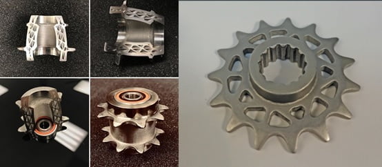
The printed drive and idler sprockets are lighter weight than a machined equivalent and have held up to severe off-road trail conditions. Metal printing allows for customization of sprocket spacing and OD which can be difficult to obtain with standard off-the-shelf components.
Similar parts can be easily printed for commercial conveyor roller chain systems as well. Tables representing the appropriate ASME/ANSI B29.1 standard can be found here: https://www.engineersedge.com/power_transmission/roller_chain_dimensions_13610.htm
 A Better Grip
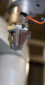 A Better Grip
3D printed end effectors are a popular user upgrade or customization for traditional manufacturing pick & place robots. For gripping on parts with internal course threads or other hard-to-handle surfaces, a custom-fit set of gripper fingers can be easily printed in metal.
Cast No Doubt
Sometimes the anticipated annual product quantity does not readily justify the expense and inventory issues of minimum casting runs. This is an area where the option to metal 3D print a component can have significant savings. Properly designed for the 3D metal printing process, a component can combine features that might otherwise require additional fasteners and assembly work.

These are just a few samples of the components that can be quickly and easily produced with Metal-X 3D printing. The range of metal alloys available to print is growing every few months. Currently, it includes stainless steel (17-4), tool steel (H-13, A2, D2), and Inconel (625). Additional stainless steels, Copper, and Titanium are in development. The ability to quickly and inexpensively print metal components will spur further innovation in design and help to bring production local to where it is used.
John Nolin
Senior Technical Representative
SolidXperts USA
Metal-X Certified Technician
SolidXperts teams can help you become true 3D experts! An additional question? Need information?
SolidXperts team is always there for you!
Any questions? Need help? Ask one of our experts.
Whether you’re ready to get started or just have a few more questions, you can contact us toll-free:
The SolidXperience Group Reveals Designs to Mass Produce Custom Ventilators in Response to the COVID-19 Crisis
St. Laurent. April 3, 2020 – A journey of a thousand miles starts with just one step. For The SolidXperience Group, that step happened on March 21st, 2020 on a couch in the socially distant living room of CEO, Alex Habrich. While watching the news with his wife, Susie, both growing increasingly concerned with the spread of COVID-19, she came across an advertisement for the Code Life Ventilator Challenge. Knowing him and the abilities of the people he employs, it was the perfect opportunity. “I know you can do this – go save lives”. That was all it took!
Our directive was clear: Design a low-cost, simple, easy-to-use, and easy-to-build ventilator that could serve COVID-19 patients, as quickly as possible. The following day Alex asked for volunteers, and a diverse team was curated from three companies and various backgrounds.
“This project is a collaboration of people from both Canada and the United States, with everyone teleworking!” – Alex P. Habrich, The SolidXperience Group CEO
Within 24 hours a team was gathered, within 8 days the designs were submitted to the challenge hosts, and within a month The SolidXperience Group will be testing a fully functional prototype of the complete OXYGEN field-ready ventilator system.
 “It feels like drowning is”, the most common report from the COVID-19 patients requiring breathing assistance, and with that imagery, we took inspiration from the simplicity of a scuba breathing apparatus. The SolidXperience Group officially began tackling the problem on March 23rd, ready to help save the world however they could.
The group quickly decided the best course of action would be to produce a machine that could both conventionally connect in a hospital setting and run as a stand-alone unit in developing countries or emergency overflow.
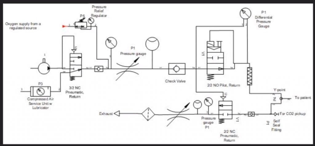 The next step was to analyze the given product specifications and start creating schematic diagrams defining the required parts and showing how those parts interact to create the desired results. With the help of the project’s panel of medical advisors, the group was able to take the initial schematic designs and modify them as a collaborative team. All online!
Then commenced several fast-paced days of editing, revision, discussion, and decision. Affordability always being a key factor. The device needed survivability, an intuitive setup and user interface, easily maintained and replaceable parts, and it needed to be kept as inexpensive to manufacture, in mass, as possible. This iterative process proceeded until March 29th at which time schematics were finalized. With the engineering in place, product design took off.
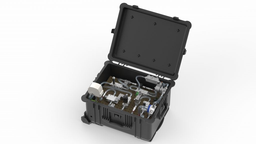
 Next, packaging: getting all the required components to fit into a manageable, transportable, robust, easy-to-operate, and reliable case. Under the pressure of the CODE LIFE contest entry submission date of March 31st, this process was successfully started and completed on March 30th. Concurrently, the digital interface was coded to manage the internal valves, solenoids, and sensors necessary to provide a clear and secure on/off readout and warning alarms.
11:58 p.m. March 31st, 2020 – The SolidXperience Group successfully submitted their entry to the CODE LIFE Ventilator Challenge and walked away with a new purpose.
Inspired by how quickly and efficiently his team was able to redesign the ventilator system while physically separated and baffled by the inflated asking price for current machines, Alex decided regardless of the outcome of the contest, The SolidXperience Group would produce their more reliable and less expensive ventilators.
![]() The fight isn’t over yet, however! In the coming weeks, several more steps need to be taken quickly to meet the hopeful deadline of May 1st for a functioning prototype. As the physical pieces of the first construction are gathered the interface code must be tested and refined, and the assembly must go through a series of tests and simulations to determine that it meets pre-set standards and can be labeled ‘medical grade’.
The fight isn’t over yet, however! In the coming weeks, several more steps need to be taken quickly to meet the hopeful deadline of May 1st for a functioning prototype. As the physical pieces of the first construction are gathered the interface code must be tested and refined, and the assembly must go through a series of tests and simulations to determine that it meets pre-set standards and can be labeled ‘medical grade’.
Both companies in The SolidXperience Group, SolidXperts, and Mecanica Solutions, eagerly look forward to stepping out into the world, continuing our thousand-mile journey, and doing what we can to help save lives all over the world.
![]() Thank you to the following team members and professionals for their part in the success of this project!
Thank you to the following team members and professionals for their part in the success of this project!
Galin Brankov
Mélanie Giroux
Heather Gliniecki
Alex Gosselin
Alex Habrich
Nikhil Kaila
Nikita Lambert
Chung Ping Lu
Alexandr Magder
Sheldon Magder
Steven Murphy
Jean-François Niaison
John Nolin
Sakineh Orangi
Rod Peck
Michael Prioriello
Alain Provost
Charles-Olivier Provost
Raphaël Reid
Erica Saunders
Benjamin Whatleym
Check back regularly and follow us on social media to never miss an update. Reach out to us with any questions.
![]()
![]()
![]()
Wash your hands, stay home, and stay safe!
Any questions? Need help? Ask one of our experts.
Whether you’re ready to get started or just have a few more questions, you can contact us toll-free:
How Does a 3D Printer Work?
By Application Specialist – Greg Bejtlich
Despite additive manufacturing being developed in the late 1980s, the term “3D printing” has been a fairly new topic in world news. Adidas is printing footwear, ICON is printing houses, and Ford is printing car parts. There are dozens of techniques for 3D printing, some for plastics and others meant for metal. The most common being FFF, or Fused Filament Fabrication. The principle of FFF requires pushing hot thermoplastic through a nozzle and onto an adhesive bed. Depending on the style of printer, the hot thermoplastic is deposited in the X and Y-axis, cools, and moves onto the next layer. Similar to our favorite childhood toy the “Etch A Sketch”, moving the print head on the X and Y-axis can create complex shapes and pathing. Repeating this process and stacking these layers can result in strong lightweight parts.
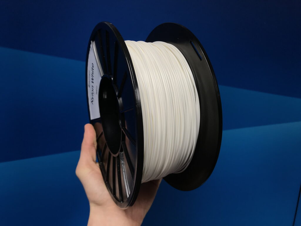
Filament
To best understand 3D printing, we’ll start with the extruded material. The material for 3D printing is called “filament” and can vary from high-impact plastics to flexible elastomers. The most common materials printed today are ABS, PLA, and Nylon. These plastics are sold in spools and range from diameters of 1.75 – 3mm. Filaments can also be supplemented with various additives such as fiberglass, ceramic, and carbon fiber. Innovators like Markforged are creating proprietary blends of thermoplastics resulting in nylon twenty-three times stronger than ABS with a 40% increase in heat deflection.
Extruder
The spools of filament are loaded into a dry box and fed into a motorized extruder. The extruder’s bearings and toothed gears ensure that the material is fed into the hot nozzle at a constant rate and does not under extrude. Most commonly the extruder is located inside of an enclosure or mounted directly on top of the print head, also called “Direct Drive”.
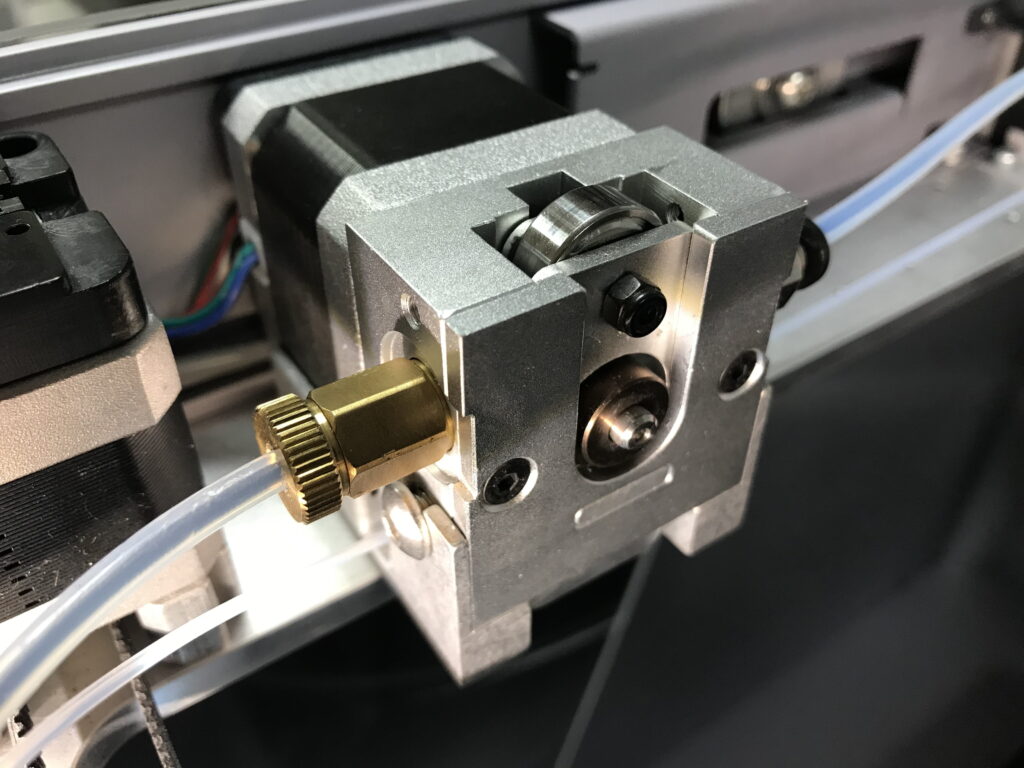
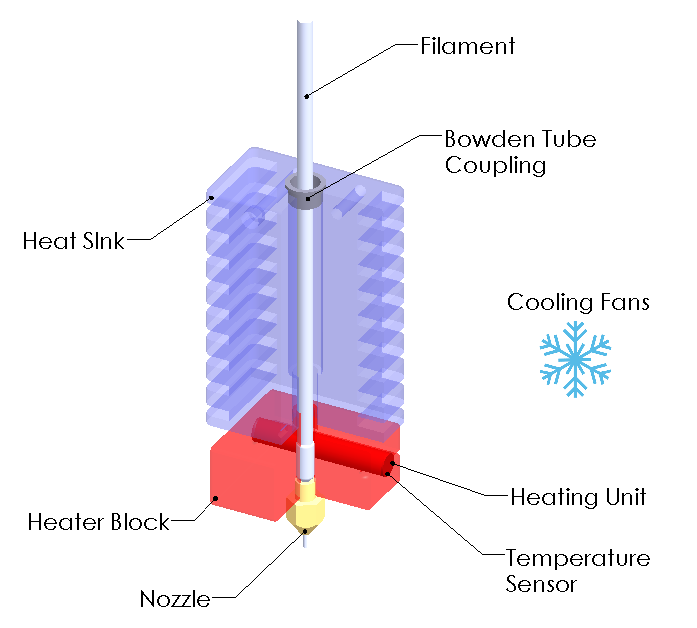
Print Head
The print head consists of six major components that handle the extrusion of the build material. The filament is forcibly fed from the extruder into the heat sink and heater block. The heater block is comprised of three simple components. An aluminum block, a heating element, and a temperature sensor – most commonly called a thermistor. The heating element warms both the heater block and the filament while the thermistor keeps the temperature in check. In its molten state, the filament is pushed through an interchangeable nozzle with diameters of .1mm to 1mm. The most common filament nozzle is .4mm
The image below shows two colored areas. The red area of the diagram is the heater block providing temperatures of 180-275°. The blue heat sink is cooled by fans and prevents molten filament and heat from creeping up the print head, also known as “heat creep”. The cooling fans also ensure that the molten filament leaving the nozzle rapidly cools and adheres to the previous layer.
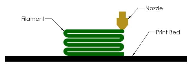
Print Bed
The last stage in a 3D printer is the print bed. The print bed is the flat and level surface where your part is built. The first layer of filament deposited on the print bed must have excellent adhesion or else the part may dislocate. Similar to constructing a house, the foundation’s quality will impact the rest of the building. To ensure proper adhesion, many printers have implemented heated build plates, tacky surfaces, or liquid adhesives. One-time use or disposable build plates can be inefficient and costly, unlike reusable build plates which require minimal cleanup and reduced waste
The material science and precision of 3D printing are key to the success of tomorrow’s technology. The ability to generate complex geometry with a broad selection of materials unlocks endless possibilities, and the next big idea could be yours.
If you’ve enjoyed this article and have an interest in creating strong 3D prints, head over to Markforged and check out the MarkTwo and X7. Their printers have an added twist on FFF and reinforce parts with kevlar, fiberglass, and carbon fiber. Creating parts lighter and stronger than 6061 Aluminum!
Any questions? Need help? Ask one of our experts.
Whether you’re ready to get started or just have a few more questions, you can contact us toll-free:
Markforged releases new trend report – “The Additive Movement has Arrived!”

WATERTOWN, MA – May 26, 2020 – Markforged, the leading manufacturer of metal and carbon fiber 3D printers, released a new Trends Report and Additive Applications Library that shows how modern manufacturers are using additive manufacturing to drive supply chain optimization and value in their organizations. The resources examine more than 100 applications within aerospace and defense, automotive, education, electronics, medical, and manufacturing; and applications across prototyping, tools and fixtures, end-use parts, and maintenance parts.
“Many of our industry peers still believe that the value of additive manufacturing is 10-15 years away when you can 3D print houses, cars, and airplanes,” said Michael Papish, VP of Marketing at Markforged. “But we’re seeing real value with customers today. Applications we’re featuring in our new Trends Report and Applications Library are already practical applications that manufacturers can use to save money, reduce downtime, and open up new revenue streams. Additive isn’t future hype, it’s already here calling from inside the house.”
Trends Report: “The Additive Movement has Arrived”
Markforged analyzed 100+ applications from around the globe across six major industries to understand how 3D printing is being used in the world today. The report found an unprecedented array of applications that demonstrate a strong, growing movement toward additive manufacturing. The applications centered around four major themes: accessibility, design freedom, physical strength and durability, and reliability — all of which are meant to improve or complement their traditional manufacturing processes and workstreams. This report discusses how we got here and the applications that are changing the way industries operate. This report authentically showcases a breadth of additive applications that are changing manufacturing, from the ability to relieve skilled workers to focus on prototyping instead of tooling to producing critical experimental test nozzles in a matter of days instead of months. The scope of applications included gives a unique view into the manufacturing industry and how additive manufacturing is driving business value.
Database: “The Additive Applications Library”
The Additive Applications Library is a comprehensive exploration tool that allows users to find real-world 3D printing use cases and examples from Markforged customers around the globe. Users can filter by industry, application, and materials to help to identify similar 3D printing opportunities in their organization and provide inspiration for new ways to improve their manufacturing processes.
More Information
- Learn more about the Additive Manufacturing Movement
- View the Markforged Additive Applications Library
- Download the full Trends Report
- Register for a webinar on the report
About Markforged
Markforged transforms manufacturing with 3D metal and continuous carbon fiber printers capable of producing parts tough enough for the factory floor. Engineers, designers, and manufacturing professionals all over the world rely on Markforged metal and composite printers for tooling, fixtures, functional prototyping, and high-value end-use production. Founded in 2013 and based in Watertown, MA, Markforged has about 250 employees globally, with $137 million in both strategic and venture capital. Markforged was recently recognized by Forbes in the Next Billion-Dollar Startups list and listed as the #2 fastest-growing hardware company in the US in the 2019 Deloitte Fast 500.
SolidXperts teams can help you become true 3D experts! An additional question? Need information?
SolidXperts team is always there for you!
Any questions? Need help? Ask one of our experts.
Whether you’re ready to get started or just have a few more questions, you can contact us toll-free: